
Spinning station of a spinning preparation machine

a technology of preparation machine and spinning station, which is applied in the direction of drafting machine, continuous wounding machine, textiles and paper, etc., can solve the problem of not being able to use known air-jet spinning machine to produce roving, and achieves the effects of reducing the risk of bending

Active Publication Date: 2017-06-13
MASCHINENFABRIK RIETER AG
View PDF12 Cites 2 Cited by
  • Summary
  • Abstract
  • Description
  • Claims
  • Application Information

AI Technical Summary

Benefits of technology

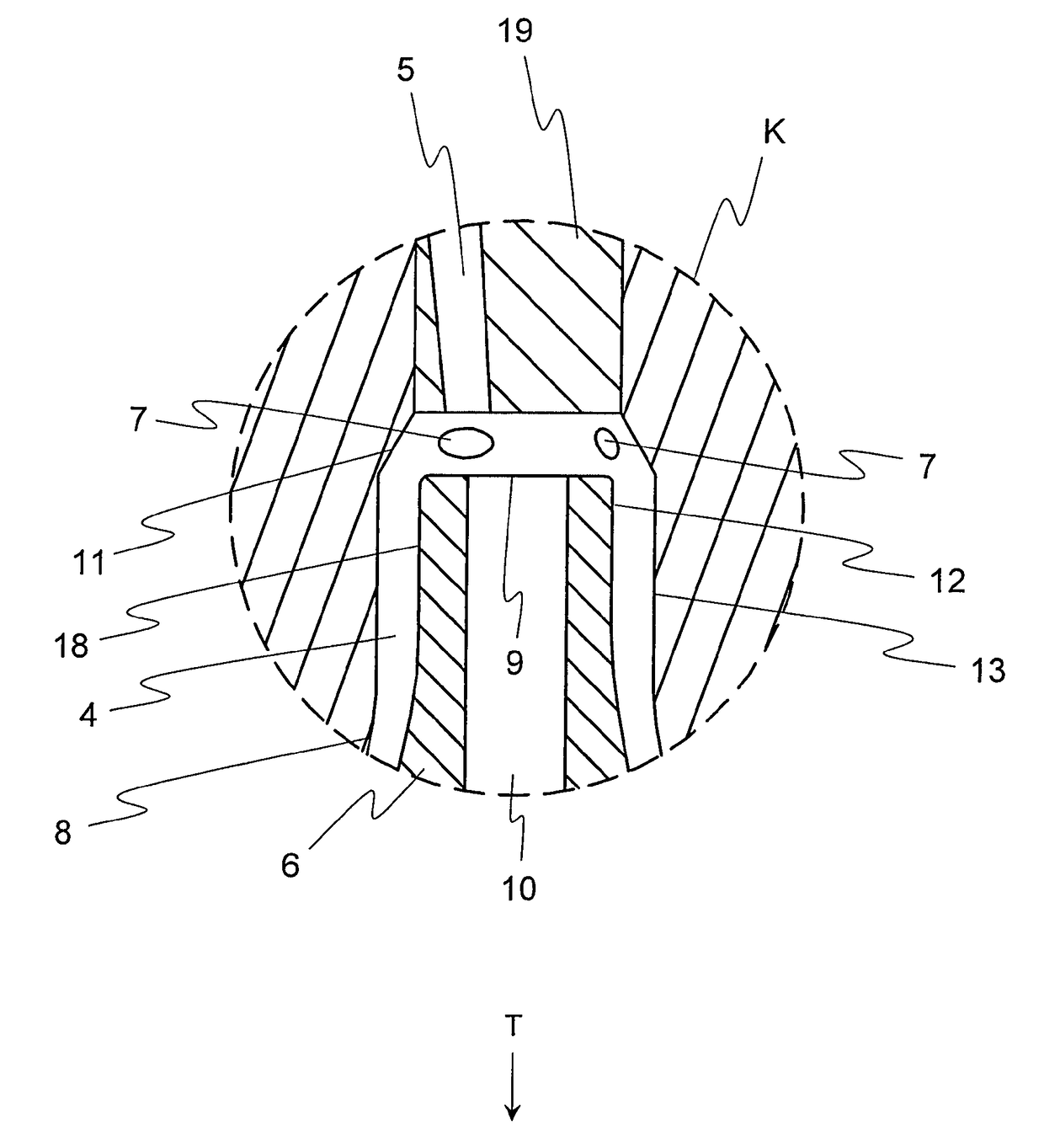
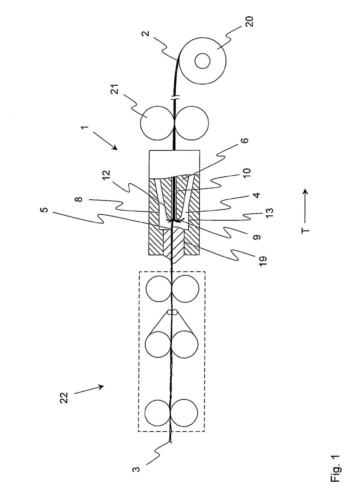
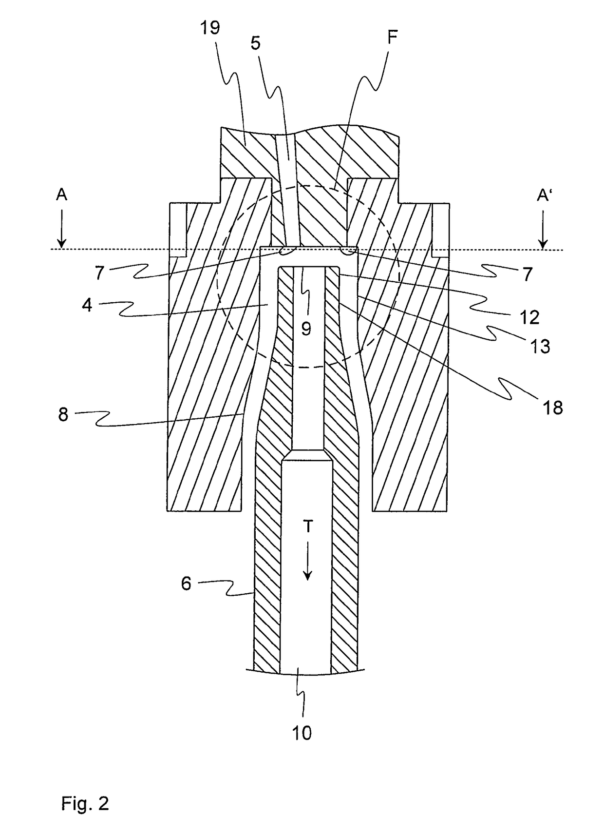
The invention is about a spinning station that uses a vortex chamber to produce a protective twist on yarn. A unique feature of the invention is that the wall of the vortex chamber has a transition section that is shaped like a truncated cone. This allows airflow to be produced by spin nozzles that extend into the gap between the yarn and the wall. This airflow impacts the fibers and ends of the fiber bundle and results in the desired protective twist. The invention is particularly useful when the yarn forming element has a cylindrical outer contour and the wall of the vortex chamber in that area has a matching cylindrical course. This creates an annular gap with a constant flow cross-section that allows for a swirled airflow and consistent production of protective twist.

Problems solved by technology

Since the production of a roving fundamentally differs from the production of a conventional yarn (because yarn and roving differ significantly in terms of strength and draftability), it is not possible to use known air-jet spinning machines to produce a roving.

Method used


Image

  • Spinning station of a spinning preparation machine
  • Spinning station of a spinning preparation machine
  • Spinning station of a spinning preparation machine

Examples


Embodiment Construction

[0033]Reference will now be made to embodiments of the invention, one or more examples of which are shown in the drawings. Each embodiment is provided by way of explanation of the invention, and not as a limitation of the invention. For example features illustrated or described as part of one embodiment can be combined with another embodiment to yield still another embodiment. It is intended that the present invention include these and other modifications and variations to the embodiments described herein.

[0034]First, it should be expressly noted that the illustrated parts of various spinning stations 1 and the upstream and downstream elements in FIG. 1 are not drawn to scale. Instead, the individual figures merely show schematic illustrations, which are intended to elucidate the basic design of the respective assemblies. In particular, the spacings, angles, and diameters that are indicated, in part, in the respective figures have values in the drawings that do not necessarily repre...


PUM

PropertyMeasurementUnit
angleaaaaaaaaaa
angleaaaaaaaaaa
angleaaaaaaaaaa

Abstract

A spinning preparation machine for producing a roving from a fiber bundle includes a vortex chamber having an infeed opening for the fiber bundle and a yarn forming element extending at least partially into the vortex chamber. The spinning station includes spin nozzles, which lead into the vortex chamber in the region of a wall enclosing the vortex chamber and via which air is introduced into the vortex chamber in a specified direction of rotation in order to set the fiber bundle, which is fed in a transport direction, into rotation in the region of an inlet mouth of the yarn forming element. The yarn forming element includes a draw-off channel, which adjoins the inlet mouth and via which the yarn can be drawn out of the vortex chamber. The wall of the vortex chamber has a transition section, which adjoins the infeed opening, and has the shape of the circumferential surface of a truncated cone, and the diameter of which increases in the transport direction. The spin nozzles lead into the vortex chamber in the region of the transition section and each has a direction of flow that is oriented in the direction of an outer surface of the wall enclosing the vortex chamber.

Description

FIELD OF THE INVENTION[0001]The present invention relates to a spinning station of a spinning preparation machine for producing a roving from a fiber bundle, wherein the spinning station includes a vortex chamber having an infeed opening for the fiber bundle fed in a transport direction and a yarn forming element extending at least partially into the vortex chamber. The spinning station includes spin nozzles, which are directed into the vortex chamber and which lead into the vortex chamber in the region of a wall enclosing the vortex chamber and via which air can be introduced into the vortex chamber in a specified direction of rotation in order to set the fiber bundle into rotation in the specified direction of rotation in the region of an inlet mouth of the yarn forming element. The yarn forming element includes a draw-off channel, which adjoins the inlet mouth and via which the yarn can be drawn out of the vortex chamber.BACKGROUND[0002]Roving is produced from slivers, which are ...

Claims


Application Information

Patent Timeline
Patent Type & Authority Patents(United States)
IPC IPC(8): D01H5/28D01H7/92D01H1/115
CPCD01H5/28D01H1/115D01H7/92
Inventor BLANKENHORN, PETER
Owner MASCHINENFABRIK RIETER AG
Learn More