
Coffee capsule

a technology of coffee capsules and capsules, applied in the field of capsules, can solve the problems of affecting the function of the capsule, affecting the quality of the capsule, and the exit opening of the capsule becoming blocked, so as to reduce the size of the inwardly directed flange, increase the size of the inlet opening, and ensure the effect of quality

Active Publication Date: 2017-06-13
ALICE ALLISON
View PDF7 Cites 0 Cited by
  • Summary
  • Abstract
  • Description
  • Claims
  • Application Information

AI Technical Summary

Benefits of technology

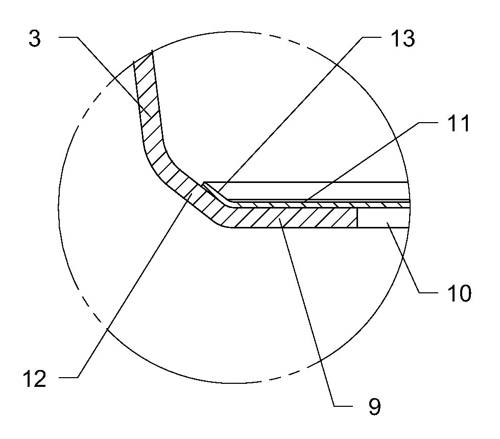
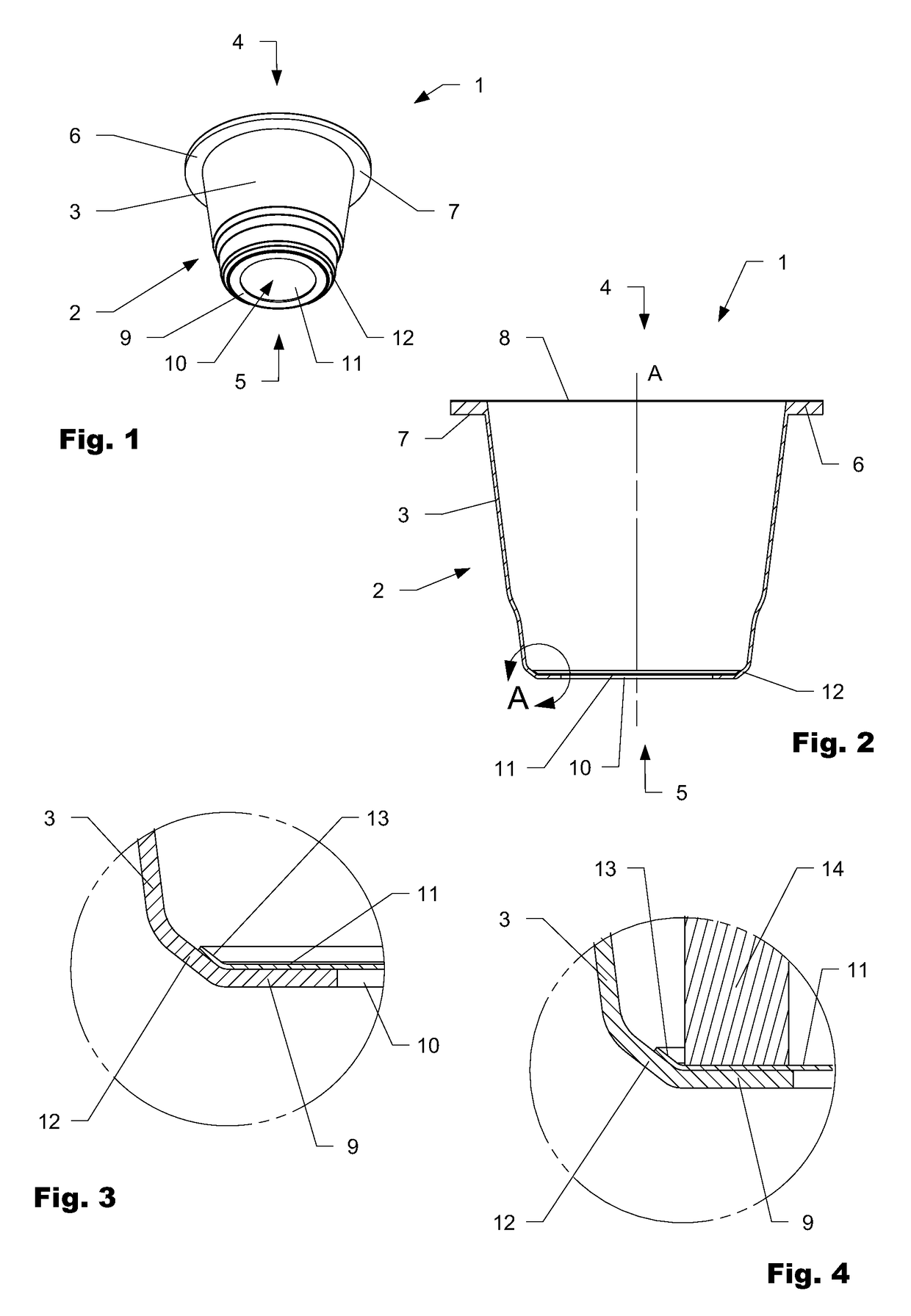
[0013]Because in the existing expresso machines several injection needles or tear-open tips are arranged in a widely spaced arrangement the inlet opening of a capsule with a plastic capsule body must have a size as large as possible in order to avoid contact with the hot injection means of the machine. On the other hand the capsule body on its narrower side must still provide a large enough area for permanently attaching the sealing membrane in an accurate and efficiently manufacturing process manner. In order to fulfil both criteria the plastic capsule comprises the inwardly directed circumferential second flange, onto which the sealing membrane is welded, and a centering ramp for correctly positioning the sealing membrane during the manufacturing process.
[0014]At the same time the inlet sealing membrane has a diameter larger than the outer diameter of the second flange. The inlet sealing membrane placed inside the capsule body during the manufacturing process is typically attached to the flange by thermo-welding with a sealing tool e.g. in the form of a welding iron pressing the sealing membrane onto the flange. Thereby the inlet sealing membrane with its oversize compared to the outer diameter of the flange (or inner diameter of the centering ramp) is bend upwards along the centering ramp and at least partially covers the lower part of the centering ramp. This upward formed bend of the sealing membrane protects the centering ramp and the capsule body from the heat of the sealing to e.g. in form of a welding iron allowing the actual welding ring to be closer to the conical side wall. This in turn allows to reduce the size of the inwardly directed flange and thereby enlarge the size of the inlet opening to avoid contact of the plastic capsule with the hot injection means of the expresso machine.
[0017]A good performance of the circumferential centering ramp for centering and bending the inlet sealing membrane has been found with a circumferential centering ramp having an off-axis angle to the longitudinal axis of the capsule of 20 to 50 degrees, preferably 35 to 40 degrees.

Problems solved by technology

This means that the capsules must be designed such that injection needles belonging to the machine do not come into contact with the plastic of the capsule, because otherwise the hot injection needles or tear-open tips would cause melting of the plastic material, which would lead to a bonding of the injection needles and thus would result in the exit openings of these needles becoming blocked.
Also, the tips heated by the hot water would soften the plastic and this plastic would form around the tip in a closing manner and handicap the correct entry of water.
The plastic residues remaining on the tips moreover lead to a blunting of the tips and these would no longer function correctly over time.
However, this is not the case and a need of a greater sealing effect between the brewing chamber of the machine and the inserted plastic capsule exists.
Disadvantageous to the shorter plastic capsules is also the smaller volumetric capacity for holding ground coffee and the necessary greater sealing effect.
The machines for these capsules however do not have hot injection needles or tear-open tips penetrating the inlet membrane and the capsule cannot be used in an expresso machine with hot injection needles or tear-open tips.

Method used


Image

  • Coffee capsule
  • Coffee capsule

Examples


Embodiment Construction

[0031]FIG. 1 and FIG. 2 show a perspective view and a sectional view of the capsule according to the invention. The capsule 1, which may be filled with roasted and ground coffee (not shown), has a truncated cone-shaped capsule body 2 made of thermoformed plastic. The capsule body 2 has a conical side wall 3 the wider end of which defines an outlet side 4 of the capsule 1 and the narrower side of which defines an inlet side 5 of the capsule 1. The inlet side 5 of the capsule 1 refers to the water entering side of the capsule in use, where hot injection means of a expresso machine penetrate into the capsule. The outlet side 4 of the capsule 1 refers to the side, where the brewed coffee leaves the capsule 1.

[0032]The capsule body 2 comprises on its wider end an outwardly directed (away from the longitudinal axis A of the capsule body) circumferential first flange 6 provided with a sealing and clamping area 7 to seal the capsule 1 against a brewing chamber of a expresso machine and hold...


PUM

PropertyMeasurementUnit
off-axis angleaaaaaaaaaa
widthaaaaaaaaaa
off-axis angleaaaaaaaaaa

Abstract

A capsule which under pressure in expresso machines is suitable for extraction of coffee, including a truncated cone-shaped capsule body of thermoformed plastic having a conical side wall, the wider end of the side wall defining an outlet side of the capsule and the narrower end of the side wall defining an inlet side of the capsule. A destructible inlet sealing membrane closes the inlet opening of the capsule body and is attached to the inside of the capsule body. The capsule body further includes a circumferential centering ramp at the narrower end of the conical side wall, which translates into an inwardly directed circumferential second flange forming the circular inlet opening, the circumferential centering ramp designed to align the inlet sealing membrane with the inlet opening before welding it to the second flange. The inlet sealing membrane has a diameter larger than the outer diameter of the second flange to be bend upwards along the centering ramp and to at least partially cover the centering ramp when welding it to the second flange. The upwards bend edge forms a heat protecting layer between a hot sealing tool and the centering ramp during welding.

Description

TECHNICAL FIELD[0001]The invention relates to capsule which under pressure in expresso machines is suitable for extraction of coffee and which may contain roasted and ground coffee.[0002]The capsule comprises a truncated cone-shaped capsule body of thermoformed plastic having a side wall. The wider end of the side wall defines an outlet side of the capsule and the narrower end of the side wall defines an inlet side of the capsule. The capsule body further has an outwardly directed circumferential first flange on the wider end of the side wall providing a sealing area towards a brewing chamber of an expresso machine; and a circular inlet opening on the narrower end of the conical side wall. A destructible outlet sealing membrane is attached to the first flange and closes the outlet side of the capsule body. A inlet sealing membrane closes the inlet opening of the capsule body and is attached to the inside of the capsule body.PRIOR ART[0003]For more than 20 years, the company Nestlé S...

Claims


Application Information

Patent Timeline
Patent Type & Authority Patents(United States)
IPC IPC(8): B65D85/804
CPCB65D85/8043B29C66/7234B29C66/71B29C66/72321B29K2705/02B29C66/612B29C66/53461B29C65/18B29C66/24221B29C65/7805B29L2031/7174B29C66/8322B65D85/8064B65D85/8049B65D85/8052B29K2023/12B29K2023/086
Inventor LANGHI, LEONARDOMORFINI, CARLO
Owner ALICE ALLISON
Learn More