
Control device and control method for internal combustion engine

a control device and control method technology, applied in the direction of electric control, machines/engines, output power, etc., can solve the problems of deterioration of exhaust gas purification performance and drivability, the amount of fuel injection from each of the injectors is reduced, and the deposit is easy to be produced at the injection hole, so as to achieve the effect of suppressing the formation of a deposi

Active Publication Date: 2017-06-06
TOYOTA JIDOSHA KK
View PDF36 Cites 3 Cited by
  • Summary
  • Abstract
  • Description
  • Claims
  • Application Information

AI Technical Summary

Benefits of technology

The patent text describes a method for controlling an internal combustion engine that reduces the formation of deposits on the engine's intake system. By injecting fuel into the engine's port injection injector during certain operating states, the method prevents the temperature around the injection hole from rising too high and causing a deposit to form. This results in improved engine performance and reduced maintenance costs.

Problems solved by technology

However, with the above-described control devices for an internal combustion engine, if the EGR device operates in an operating state where port injection is not carried out and only in-cylinder direct injection is carried out, the temperature around injection holes of port injection injectors exposed to the inside of an intake passage rises, possibly leading to occurrence of a state where a deposit is easily produced at the injection holes of the port injection injectors.
Therefore, there are concerns about deterioration of exhaust gas purification performance and drivability because, when the state where a deposit is easily produced frequently occurs or the operating state of only in-cylinder direct injection continues for a long time, a fuel injection amount from each of the port injection injectors decreases due to the produced deposit.

Method used


Image

  • Control device and control method for internal combustion engine
  • Control device and control method for internal combustion engine
  • Control device and control method for internal combustion engine

Examples


Embodiment Construction

[0034]Hereinafter, an embodiment of the invention will be described with reference to the accompanying drawings.

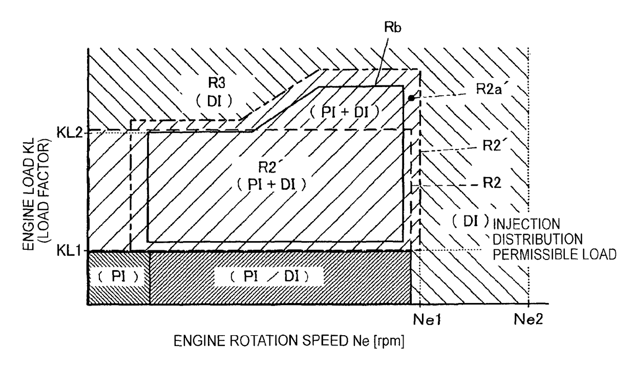
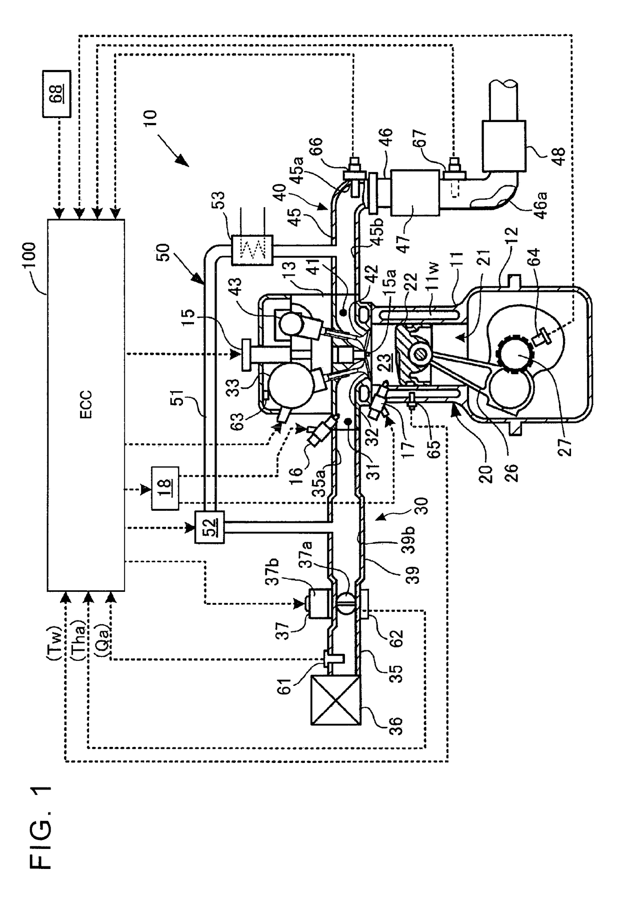
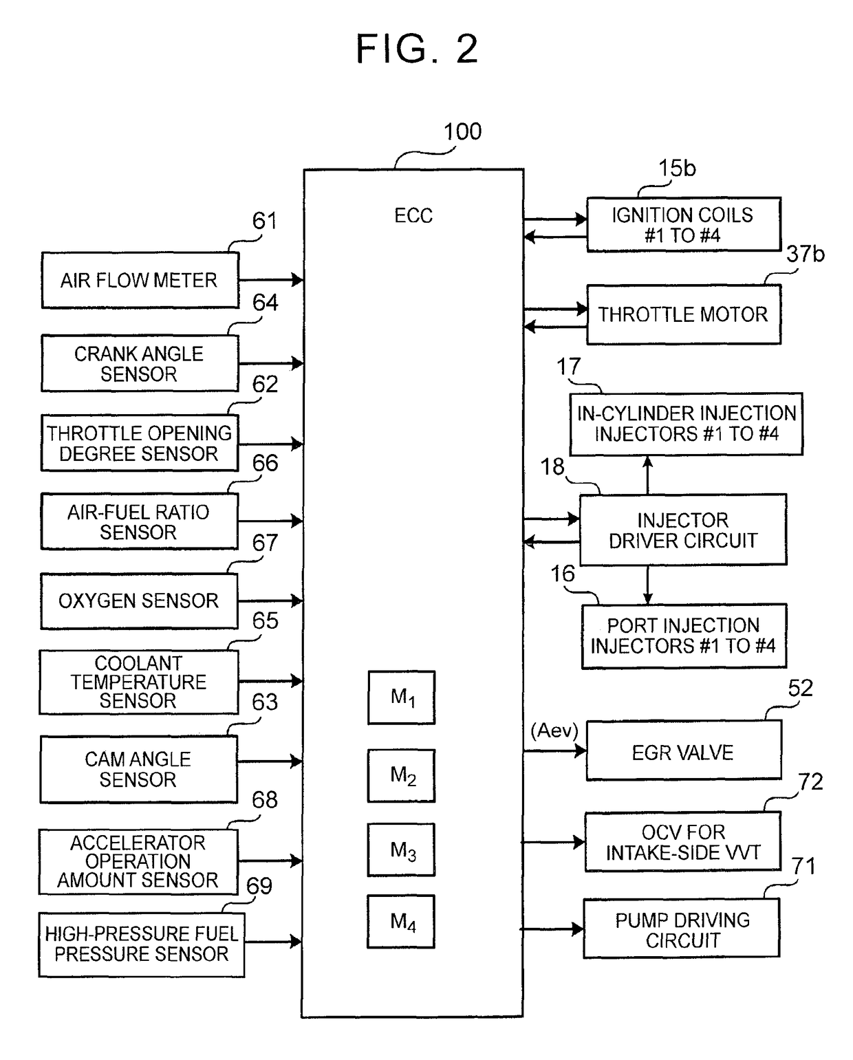
[0035]FIG. 1 to FIG. 4 show the configuration of an internal combustion engine and a control device therefor according to the embodiment of the invention. FIG. 5 to FIG. 7 show the flows of a plurality of control programs that are executed by the control device. The control device for an internal combustion engine according to the present embodiment is equipped for a spark ignition multicylinder internal combustion engine, for example, in-line four-cylinder four-cycle gasoline engine (hereinafter, referred to as engine), mounted on an automobile (vehicle).

[0036]First, the configuration will be described.

[0037]As shown in FIG. 1 and FIG. 2, the control device for an internal combustion engine according to the present embodiment includes an engine 10 that is the internal combustion engine, and has an engine control computer (hereinafter, ECC) 100.

[0038]The engine 10 includes...


PUM


Abstract

A control device for an internal combustion engine includes: an EGR control unit executing open / close control over an EGR valve on the basis of an operating state of the engine; and a fuel injection control unit carrying out at least one of port injection and in-cylinder direct injection by operating at least one of a port injection injector and an in-cylinder direct injection injector on the basis of the engine operating state. The fuel injection control unit sets an EGR non-operation in-cylinder direct injection region, in which the port injection is stopped and the in-cylinder direct injection is carried out while the EGR valve is closed, within an operation range of the engine, and sets part of an EGR operation port injection permissible region, in which at least the port injection is carried out while the EGR valve is open, within the EGR non-operation in-cylinder direct injection region.

Description

BACKGROUND OF THE INVENTION[0001]1. Field of the Invention[0002]The invention relates to a control device and control method for an internal combustion engine and, more particularly, to a control device and control method for an internal combustion engine, which execute fuel injection control over the internal combustion engine that uses both port injection and in-cylinder direct injection.[0003]2. Description of Related Art[0004]There is a multicylinder internal combustion engine (hereinafter, referred to as engine) that is mounted on a vehicle and that is of a dual injection type in which both port injection injectors and in-cylinder direct injection injectors are provided. The engine of this type is equipped with a fuel injection control device that is able, to control port injection (fuel injection into ports) and in-cylinder direct injection (direct fuel injection into cylinders) with the use of both types of injectors.[0005]There is such a control device for an internal combus...

Claims


Application Information

Patent Timeline
Patent Type & Authority Patents(United States)
IPC IPC(8): F02D41/30F02D41/00F02D13/02F02M61/14
CPCF02D41/3094F02D13/0276F02D41/005F02D41/0057F02D41/3029F02D41/3076F02M61/145Y02T10/47Y02T10/40
Inventor MASHIKI, ZENICHIRO
Owner TOYOTA JIDOSHA KK
Learn More