
Rotary turbo rocket

a rotary turbo rocket and turbojet technology, which is applied in the field of turbojet combined with rotary rockets, can solve the problems of high propellant consumption rate, inability to operate outside the atmosphere, and increase the complexity and mass of the overall engine, so as to alleviate or eliminate one or more deficiencies, disadvantages, and the effect of reducing the number o

Active Publication Date: 2017-05-16
BOSSARD JOHN
View PDF30 Cites 1 Cited by
  • Summary
  • Abstract
  • Description
  • Claims
  • Application Information

AI Technical Summary

Benefits of technology

[0010]Accordingly, embodiments of the present invention preferably seek to mitigate, alleviate or eliminate one or more deficiencies, disadvantages or issues in the art, such as those identified above, singly or in any combination by providing a Rotary Turbo Rocket (RTR) comprising a turbojet co-axially integrated with a rotary rocket. The turbojet may operate in any mode available to turbojet engines, including subsonic, transonic, and supersonic flight speeds, by adapting the air inlet and turbomachinery operation according to known methods. The rotary rocket may be supplied with fuel and oxidizer at any mixture ratio for use at any time whether in atmosphere or not. When operated with a fuel-rich mixture ratio, the rotary rocket functions as a fuel-injector for an afterburning turbojet mode. Furthermore, when using a fuel-rich mixture ratio, the rotary rocket can produce shaft power to drive the compressor, burning the fuel-rich mixture in the afterburner, and thus allowing the RTR to operate in an Air Turbo Rocket mode. Accordingly, the RTR is able to operate as a turbojet, an afterburning turbojet, an Air Turbo Rocket, a rotary rocket, together or separately, in any combination. Furthermore, the RTR is able to transition between any of these modes abruptly or in a variable or continuous or gradual manner.

Problems solved by technology

A primary disadvantage of an ATR is its high propellant consumption rate, relative to a turbojet.
Although the engine uses stored oxygen as an oxidizer, this engine uses atmospheric oxygen in all operational modes and is therefore not capable of operation outside the atmosphere.
Although this engine concept combines a jet engine with a rocket engine, allowing both air-breathing and rocket propulsion modes, no advantage is taken of combining the required turbomachinery of the jet and rocket engines, and thus the concept requires separate turbomachinery assemblies for the jet and rocket engines, which greatly increases complexity and mass of the overall engine.
Because the rocket chambers are integral with the pump elements, rotary rockets also eliminate the need for high-pressure, high-speed rotating seals, which is a very challenging and expensive issue for conventional turbopump-fed rocket engines.
One disadvantage of a rotary rocket is that there is no rotation at start-up so some means other than rotation must be provided for pumping propellants at engine start.
Another disadvantage of rotary rockets is that the rocket chambers are heavier than conventional rocket chambers because they must be designed to withstand the centrifugal forces generated during the rotation of the rocket chambers.
Despite the development of the aforementioned propulsion technologies, high speed endo-atomospheric, trans-atmospheric and exo-atomospheric vehicles powered by TBCC engines have not yet come into widespread use.
TBCC engines which are only air-breathing are limited in their maximum flight speeds and altitudes, and cannot fly exo-atmospherically.
Alternatively, rocket engines have too high of a propellant-usage rate for long-range endo or trans-atmospheric flights.

Method used


Image

  • Rotary turbo rocket
  • Rotary turbo rocket
  • Rotary turbo rocket

Examples


Embodiment Construction

[0019]Specific embodiments of the invention now will be described with reference to the accompanying drawings. This invention may, however, be embodied in many different forms and should not be construed as limited to the embodiments set forth herein; rather, these embodiments are provided so that this disclosure will be thorough and complete, and will fully convey the scope of the invention to those skilled in the art. The terminology used in the detailed description of the embodiments illustrated in the accompanying drawings is not intended to be limiting of the invention. In the drawings, like numbers refer to like elements.

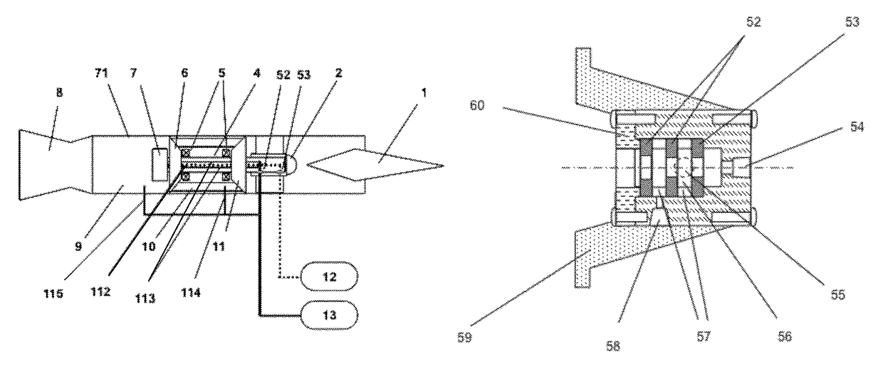
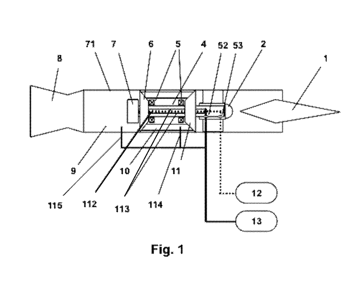
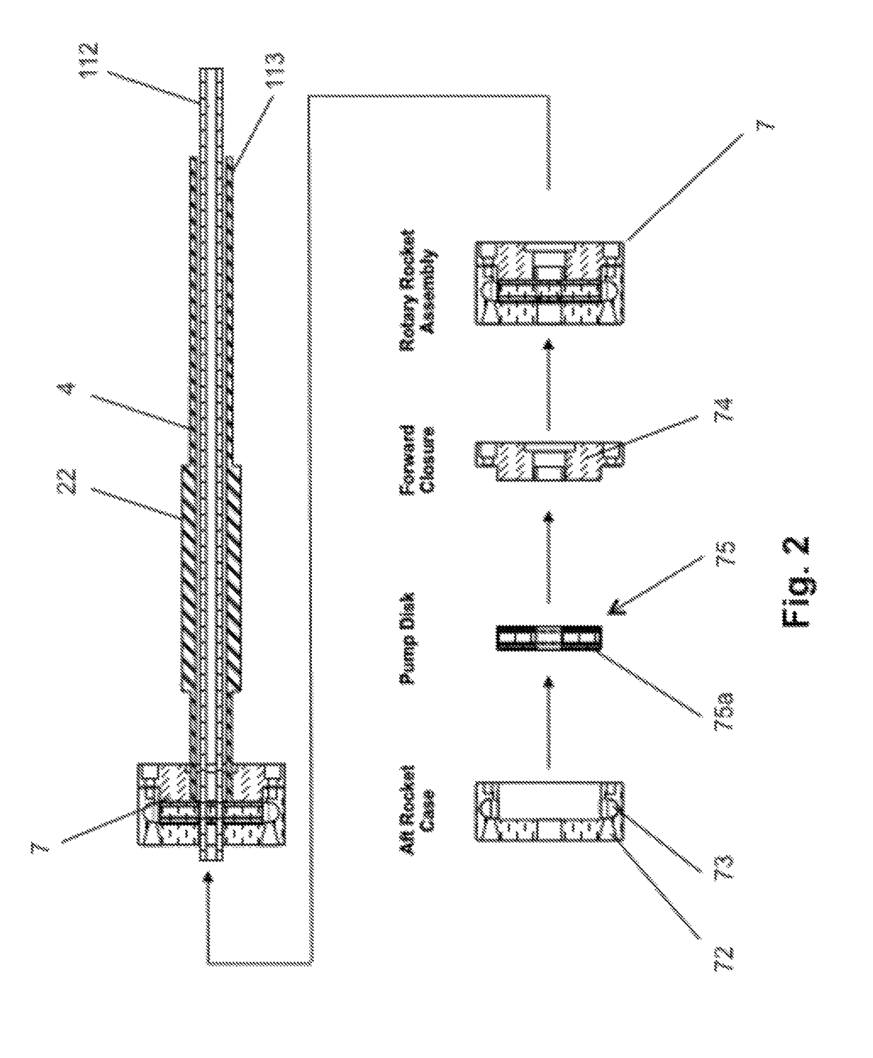
[0020]FIG. 1 illustrates the basic configuration of one embodiment of a Rotary Turbo Rocket (RTR) comprising a turbojet and a rotary rocket 7 contained in an outer casing 71. The turbojet comprises a compressor 11, a combustion chamber 10, turbine 6, and bearings 5. The rotary rocket 7 is positioned aft of (behind) the turbojet. The compressor 11, turbine 6, b...


PUM


Abstract

A turbojet is combined with a co-axially integrated rotary rocket to form a propulsion system called a Rotary Turbo Rocket that can function as a turbojet, as an afterburning turbojet, as an Air Turbo Rocket, or as a rotary rocket. The Rotary Turbo Rocket can operate in any of these propulsion modes singularly, or in any combination of these propulsion modes, and can transition continuously or abruptly between operating modes. The Rotary Turbo Rocket can span the zero to orbital flight velocity speed range and / or operate continuously as it transitions from atmospheric to space flight by transitioning between operating modes.

Description

BACKGROUND OF THE INVENTION[0001]Field of the Invention[0002]The current invention relates to a class of propulsive engines known as turbine-based-combined-cycle (TBCC) engines and more particularly to a turbojet combined with a rotary rocket.[0003]Description of the Prior Art[0004]The need for endo-atomospheric, trans-atmospheric, and exo-atomospheric vehicles has created interest in propulsion systems that can operate in, through, and out of the atmosphere. A number of propulsion systems designed to operate in atmosphere have been proposed. Turbine-based-combined-cycle (TBCC) engines, for example, are propulsive engines that have elements of both turbojet engines, which use atmospheric air as the main constituent of their reaction mass, and rocket engines, which carry all of their reaction mass.[0005]An Air Turbo Rocket (ATR) is a type of TBCC engine which combines a conventional solid or liquid propellant rocket-type gas generator with a conventional turbojet in such a way that h...

Claims


Application Information

Patent Timeline
Patent Type & Authority Patents(United States)
IPC IPC(8): F02K9/78F02K9/66
CPCF02K9/78F02K9/66
Inventor BOSSARD, JOHN
Owner BOSSARD JOHN
Learn More