
Cluster solid state drives

Active Publication Date: 2017-04-11
HEWLETT-PACKARD ENTERPRISE DEV LP
View PDF11 Cites 11 Cited by
  • Summary
  • Abstract
  • Description
  • Claims
  • Application Information

AI Technical Summary

Benefits of technology

This patent describes a method of arranging and connecting multiple solid state drives (SSDs) within a commercially available chassis. The goal is to make the most efficient use of space within the chassis while still utilizing the standard slots. The patent also mentions the use of M.2-standard SSDs, but also considers other standards as well. The technical effect of this patent is a more compact and efficient way to connect multiple SSDs within a chassis.

Problems solved by technology

A challenge is how to design a cost effective storage system in which a larger percentage of data is stored using SSDs.

Method used


Image

  • Cluster solid state drives
  • Cluster solid state drives
  • Cluster solid state drives

Examples


Embodiment Construction

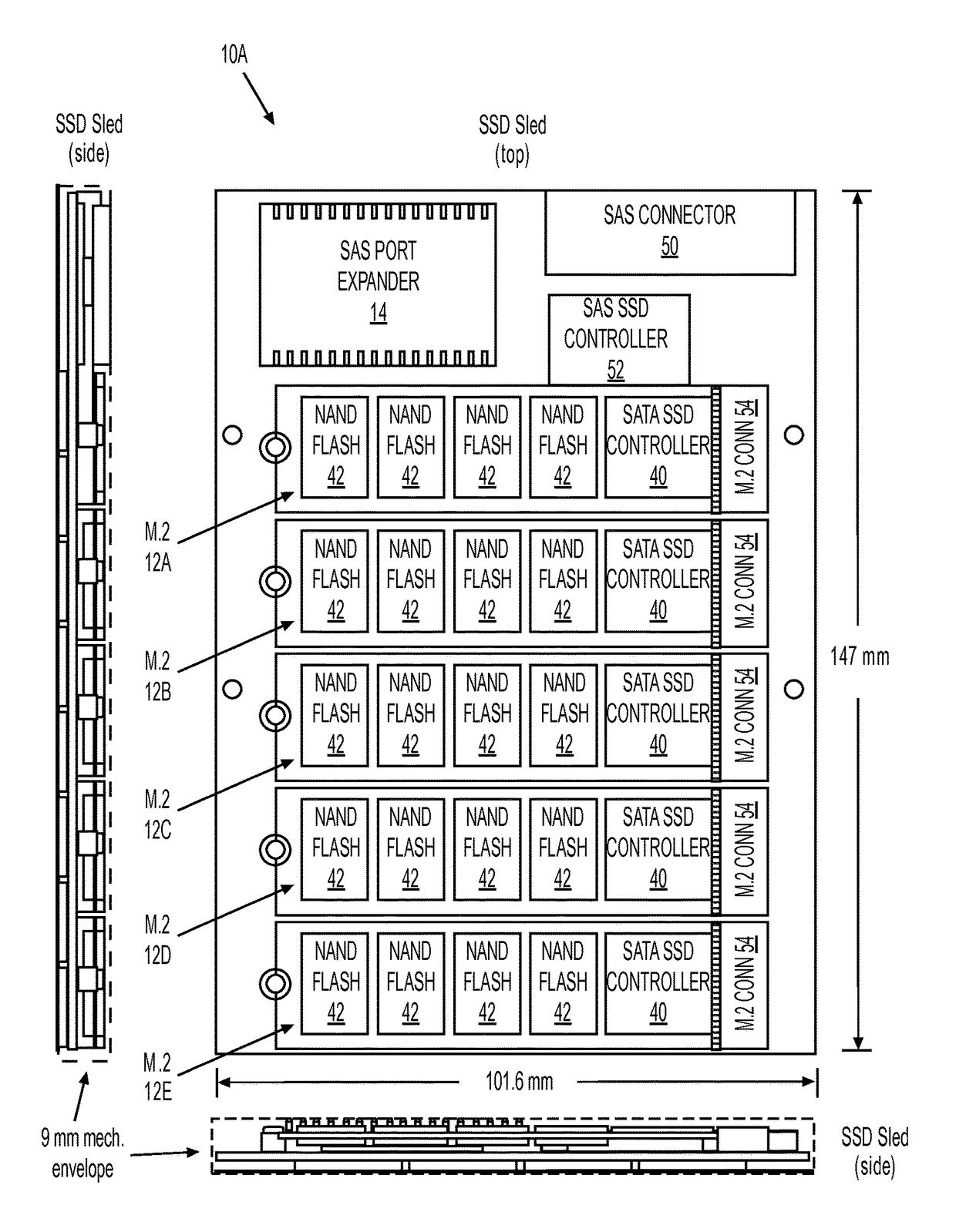
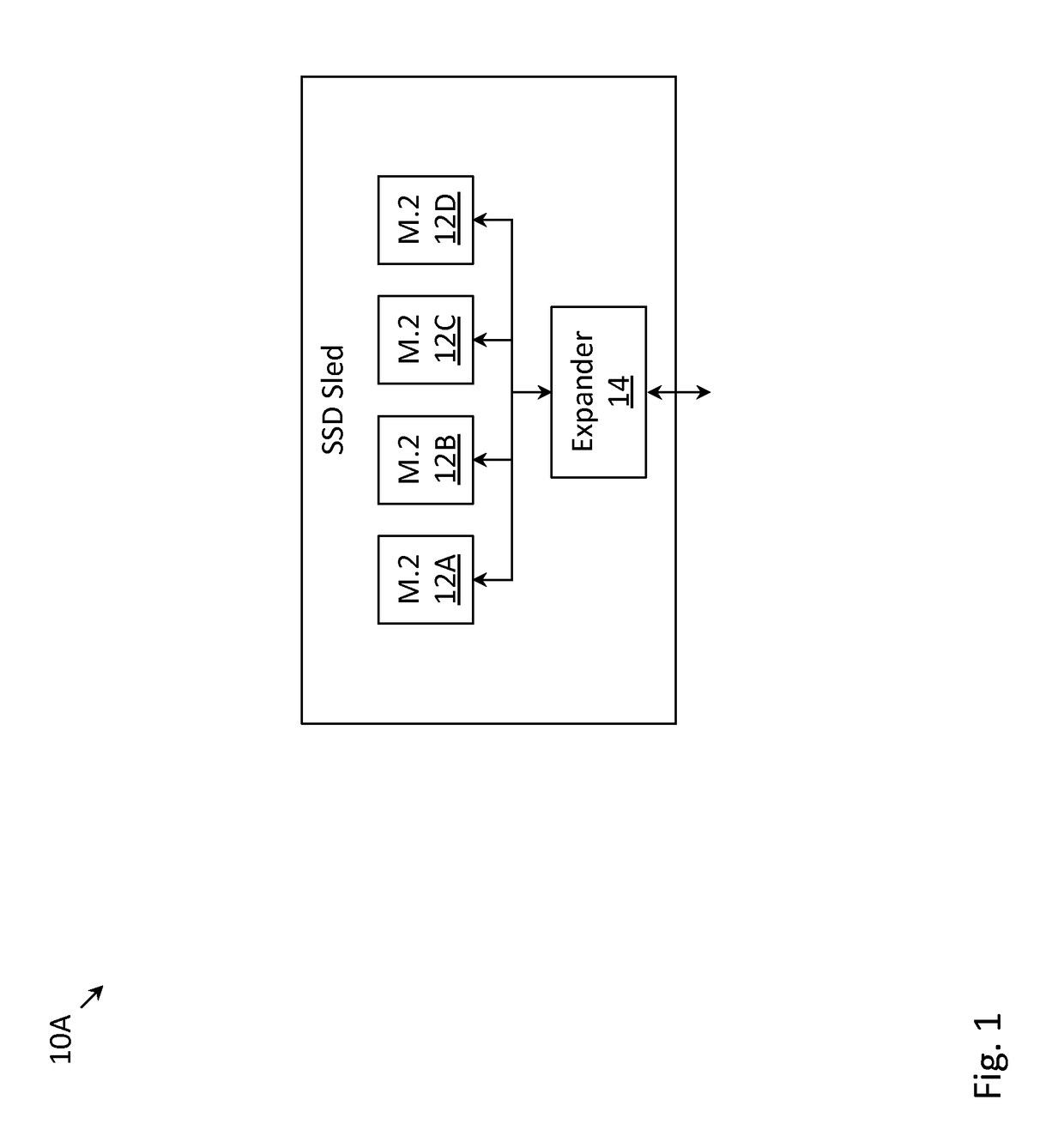
[0010]FIG. 1 depicts SSD sled 10A with a plurality of M.2 SSD modules (12A, 12B, 12C, 12D), in accordance with one embodiment. As depicted in FIG. 1, the plurality of M.2 SSD modules (12A, 12B, 12C, 12D) may be communicatively coupled to port expander 14, which compactly arranges the input / output (I / O) signals of all of the M.2 SSD modules onto a set of I / O ports. Port expander 14, however, is just one mechanism to compactly arrange the I / O signals, and in another embodiment, port expander 14 may be replaced with a non-volatile memory express (NVMe) peripheral component interconnect express (PCIe) interface. While SSD sled 10A may contain four M.2 SSD modules in the embodiment depicted in FIG. 1, SSD sled 10A may contain a different number of M.2 SSD modules in other embodiments. See, e.g., the embodiment in FIGS. 3-4 with five M.2 SSD modules (described below).

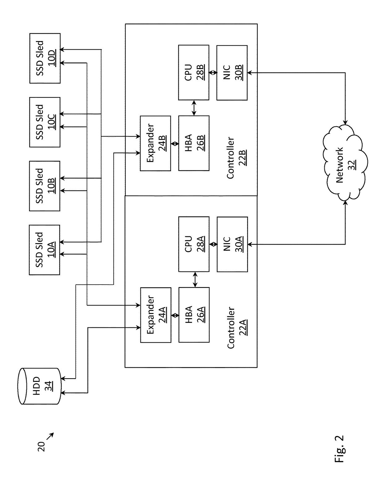
[0011]FIG. 2 depicts storage system 20, in accordance with one embodiment. As depicted in FIG. 2, a plurality of SSD sleds ...


PUM


Abstract

Described herein are techniques for arranging a plurality of M.2 solid state drive (SSD) modules and flash storage elements into a compact form factor. On a first side of an SSD sled, a plurality of M.2 SSD modules may be communicatively coupled to a port expander. On a second side of the SSD sled, a plurality of flash storage elements (not packaged into M.2 SSD modules) may be present. A plurality of SSD sleds (with the above-described characteristics) may be sized so as to collectively fit into a single hard disk drive (HDD) compatible compartment of a chassis.

Description

RELATED APPLICATIONS[0001]This application is a non-provisional patent application of and claims priority to U.S. Provisional Application No. 61 / 989,452, filed 6 May 2014, which is assigned to the assignee of the present invention and is incorporated by reference herein.FIELD OF THE INVENTION[0002]The present invention relates to methods for arranging a plurality of solid state drives (SSDs) into a compact form factor, and storage systems in which a plurality of SSDs are arranged into a compact form factor.BACKGROUND[0003]Most commercially available storage systems generally include those with disk drives (e.g., hard disk drives (HDDs)), those with solid state drives (SSDs) (e.g., flash drives), and those with a combination of the two. Disk drives have the advantage of being lower cost than SSDs. On the other hand, it is typically faster to read data from an SSD than a disk drive. With the advancement of semiconductor technology, SSDs are becoming cheaper to manufacture. Accordingly...

Claims


Application Information

Patent Timeline
Patent Type & Authority Patents(United States)
IPC IPC(8): G06F12/00G06F3/06
CPCG06F3/0626G06F3/061G06F3/0655G06F3/0658G06F3/0688
Inventor MEHTA, VARUNMCKNIGHT, TOM
Owner HEWLETT-PACKARD ENTERPRISE DEV LP
Learn More