
Vehicle lifting system with central controller and method of use thereof

a technology of vehicle lifting and central controller, applied in the direction of lifting frames, lifting devices, etc., can solve the problems of wireless signals being disturbed by large structures, and achieve the effect of improving communication between individual lifting columns

Active Publication Date: 2017-04-04
STERTIL
View PDF38 Cites 22 Cited by
  • Summary
  • Abstract
  • Description
  • Claims
  • Application Information

AI Technical Summary

Benefits of technology

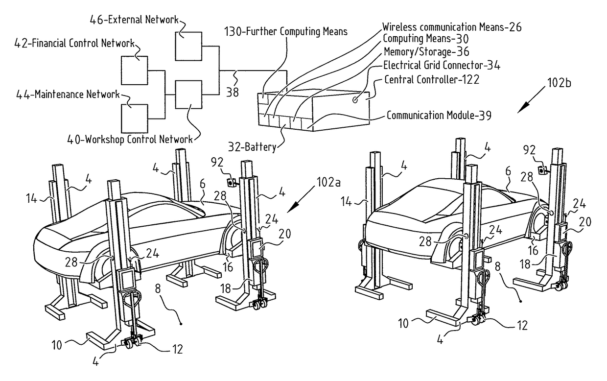
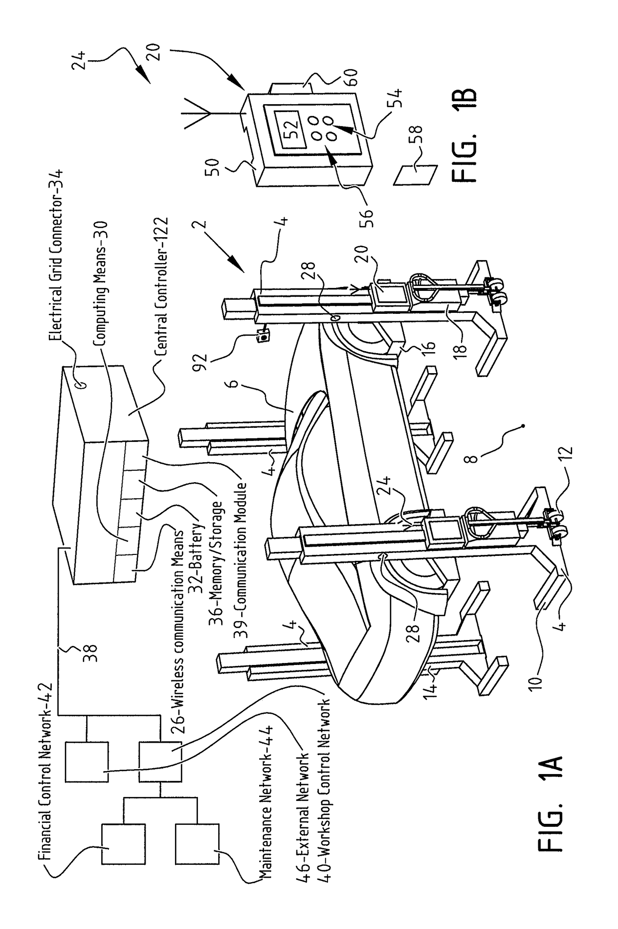
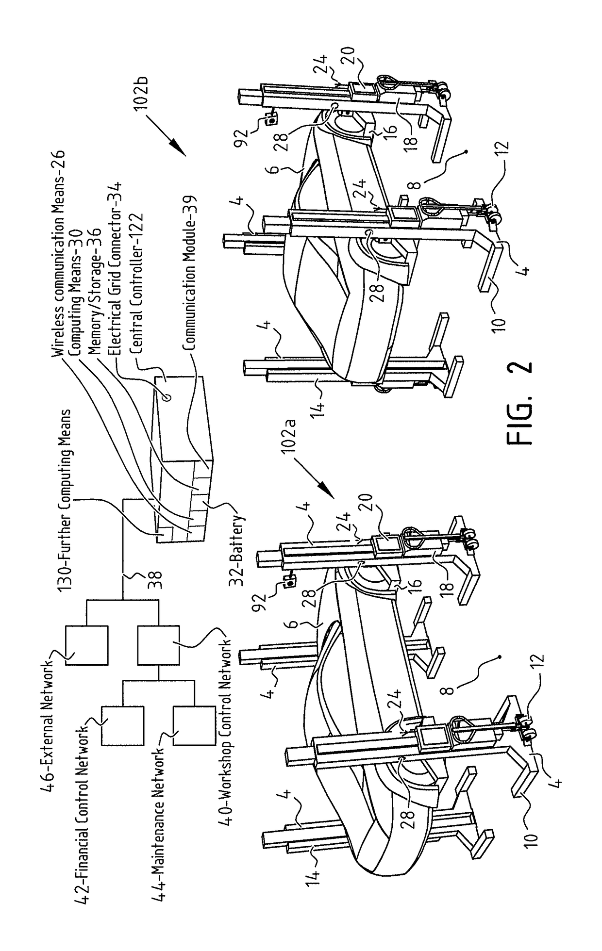
[0017]The central controller can determine and communicate required control actions to the individual lifting devices, such as moveable lifting columns. The central controller can use computing means, such as a processor, to determine the required and / or desired control actions. This may involve comparing height measurements from different lifting devices and calculating a corrective action, if necessary. The central controller can be positioned such that all communication between an individual lifting device and the central controller has a minimum risk of being disturbed. This contributes to a safe and robust operation with the lifting devices. For example, the central controller can be positioned above a group of lifting devices it is controlling. This may involve attaching the central controller to a ceiling of the workshop, for example.
[0051]In a further presently preferred embodiment the release signal can be provided after a clearance signal has been received from a clearance system. In one of the possible embodiments, a release signal can be generated by the central controller, while the clearance signal can be generated remotely by the clearance system. This clearance system preferably provides the clearance signal in response to receiving and / or generating debiting instructions. This may involve the use of pre-paid cards, generating debiting instructions etc. In a possible embodiment according to the invention the clearance signal can actually comprises a payment. An example of such payment is the use of a pre-paid card and / or payment by mobile phone. Optionally, this payment is directly made at the lifting system. This enables a direct coupling between an individual lifting operation and the cost / payments for the use thereof.

Problems solved by technology

In a workshop wireless signals can be disturbed by large structures, such as vehicles, and other wireless devices sending and receiving signals.
Due to disturbed communication lifting systems do not operate effectively and hazardous situations may result from such disturbed communication.

Method used


Image

  • Vehicle lifting system with central controller and method of use thereof
  • Vehicle lifting system with central controller and method of use thereof
  • Vehicle lifting system with central controller and method of use thereof

Examples


Embodiment Construction

[0061]The following description is merely exemplary in nature and is in no way intended to limit the invention, its application, or uses. While the disclosure is described as having exemplary attributes and applications, the present disclosure can be further modified. This application is therefore intended to cover any variations, uses, or adaptations of the disclosure using its general principles. Further, this application is intended to cover such departures from the present disclosure as come within known or customary practice of those skilled in the art to which this disclosure pertains and which fall within the limits of the appended claims. Accordingly, the following description of certain embodiments and examples should be considered merely exemplary and not in any way limiting.

[0062]The lift control system of the present invention is suitable for use with lift systems comprising any number of lifting devices that require height control columns, including systems having one, ...


PUM


Abstract

A lifting system and method of use thereof for lifting a vehicle. The lifting system includes one or more lifting devices. Each lifting device includes a frame with a carrier configured for carrying the vehicle, a drive for driving the carrier in at least one of the ascent or decent of the carrier, a transmitter / receiver for wireless communication with a central controller that is configured for centrally controlling the one or more lifting devices, and a sensor for measuring at least one of the ascent or descent of the carrier. The central controller includes a transmitter / receiver for communication with individual lifting devices and a processor for determining required control actions for individual lifting devices. The central controller and / or at least one of the lifting devices includes a user input. The central controller controls two or more independent groups of selected lifting devices.

Description

CROSS-REFERENCE TO RELATED APPLICATIONS[0001]This application claims priority to U.S. provisional application No. 61 / 983,637, filed Apr. 24, 2014, and to Dutch patent application no. NL 2012679, also filed Apr. 24, 2014, both entitled “LIFTING SYSTEM WITH CENTRAL CONTROLLER FOR LIFTING A VEHICLE WITH MOVEABLE LIFTING COLUMNS, AND METHOD THEREFOR”, both of which are incorporated herein by reference.BACKGROUND OF THE INVENTION[0002]Field of the Invention[0003]The invention relates to a vehicle lifting system and more specifically to a system comprising one or more moveable lifts or lifting devices, such as lifting columns. In general, lifting systems are specifically used for lifting trucks and busses or other vehicles.[0004]Description of Related Art[0005]A lifting column known from practice comprises a frame with a carrier that is connected to a drive for moving the carrier upwards and downwards. In the ascent mode, hydraulic oil is pumped to a cylinder for lifting the carrier and, ...

Claims


Application Information

Patent Timeline
Patent Type & Authority Patents(United States)
IPC IPC(8): B66F7/10B66F7/20B66F3/46B66F13/00
CPCB66F3/46B66F7/20B66F13/00
Inventor VAN HOUTEN, RUDOLF JACOBUS ANTONIUSDE JONG, JURJEN JAN
Owner STERTIL
Learn More