
Acoustic wave filter with enhanced rejection

a filter and acoustic wave technology, applied in the field of microwave filters, can solve the problems of excessive loss at these frequencies, affecting the size and cost of the resonator for a given, and corresponding compromise in filter steepness or selectivity

Active Publication Date: 2017-03-28
MURATA MFG CO LTD
View PDF19 Cites 28 Cited by
  • Summary
  • Abstract
  • Description
  • Claims
  • Application Information

AI Technical Summary

Benefits of technology

The acoustic filter described in this patent has capacitive elements that improve the sharpness of the lower and upper edges of the passband. These elements can be placed in parallel with the in-line and in-shunt acoustic resonators. The capacitance of the elements should be between 0.5 pF and 2.0 pF, specifically between 0.8 pF and 1.5 pF. This design helps to improve the quality of the acoustic filter and enhance its performance.

Problems solved by technology

The technical problem addressed in this patent text is the need for filters with improved performance in mobile devices, particularly in the front-end receive filter, while also reducing the size, cost, and power consumption of the filter. This is achieved by sharpening the line shapes of filter passbands and ensuring that discontinuities in the frequency response reside as far outside of the passband as possible. The use of acoustic resonator filters is preferred for this purpose due to their low insertion loss and compact size. However, there are limitations in the steepness and selectivity of conventional acoustic resonator filters, which can compromise filter performance. The patent text proposes a solution to overcome these limitations and improve filter performance.

Method used


Image

  • Acoustic wave filter with enhanced rejection
  • Acoustic wave filter with enhanced rejection
  • Acoustic wave filter with enhanced rejection

Examples


Embodiment Construction

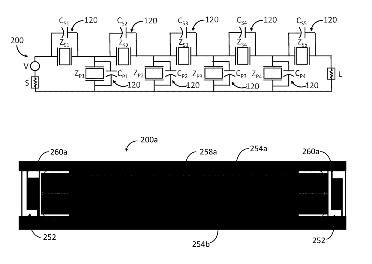
[0044]The present disclosure describes a design technique that enhances the rejection on one or both sides of a passband of an acoustic wave (AW) microwave filter, such as, e.g., a surface acoustic wave (SAW), bulk acoustic wave (BAW), film bulk acoustic resonator (FBAR), or microelectromechanical system (MEMS) filter. This technique uses standard manufacturing techniques and can be implemented without altering the overall size of the chip on which the microwave filter is disposed. This technique can be very useful when implemented in band gap contiguous duplexers. Increased rejection is also achieved in the neighboring band. Frequencies further out-of-band, both above and below the passband, can be rejected more, which will help in preventing unwanted signals interfering with the performance of the front-end receiver. Narrow band filters / duplexers can be designed, which increases the number of designs possible for a given piezoelectric material. The acoustic microwave filter may op...


PUM


Abstract

A narrow-band acoustic filter comprises an input and an output, and at least one acoustic resonator pair coupled between the input and the output. Each of the acoustic resonator pair(s) comprises at least one in-line acoustic resonator and in-shunt acoustic resonator that operate together to create a nominal passband. The acoustic filter further comprises at least one capacitive element in parallel with one of the in-line acoustic resonator and the in-shunt acoustic resonator of each of the acoustic resonator pair(s), thereby sharpening one of a lower edge and an upper edge of the nominal passband.

Description


Claims


Application Information

Patent Timeline
Owner MURATA MFG CO LTD
Learn More