Apparatus for high bandwidth current sensing

a technology of high-bandwidth current and sensing apparatus, which is applied in the direction of measurement devices, magnitude/direction of magnetic fields, instruments, etc., can solve the problems of poor control system bandwidth, potential damage, and difficult to achieve the effect of wide-band current sensing and low permeability cor

Active Publication Date: 2017-03-28
GE AVIATION SYST LLC
View PDF8 Cites 1 Cited by
  • Summary
  • Abstract
  • Description
  • Claims
  • Application Information

AI Technical Summary

Problems solved by technology

At higher power levels resistive sensing is problematic due to power dissipation or sensing very small voltages and Hall effect sensors typically have inadequate bandwidth.
This leads to poor control system bandwidth and the potential for damage under fault conditions.

Method used


Image

  • Apparatus for high bandwidth current sensing
  • Apparatus for high bandwidth current sensing
  • Apparatus for high bandwidth current sensing

Examples


Embodiment Construction

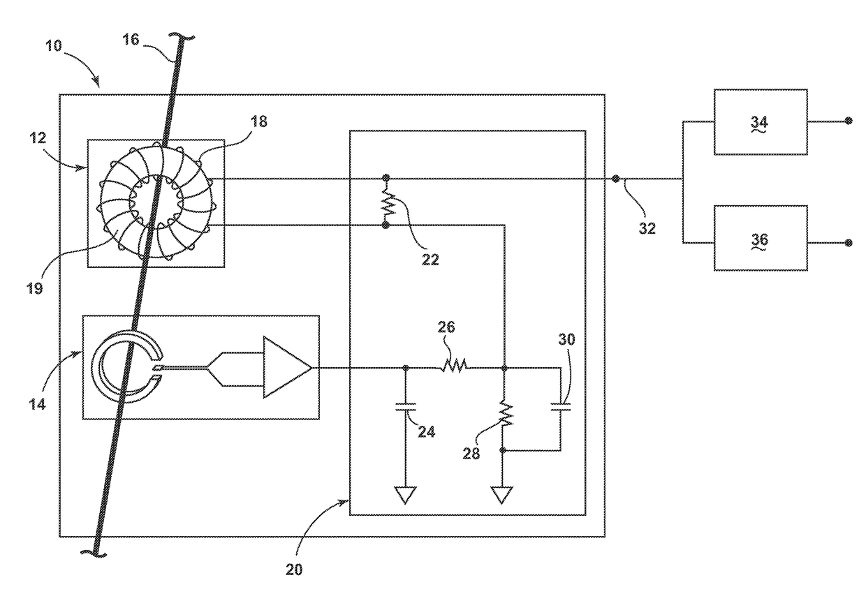
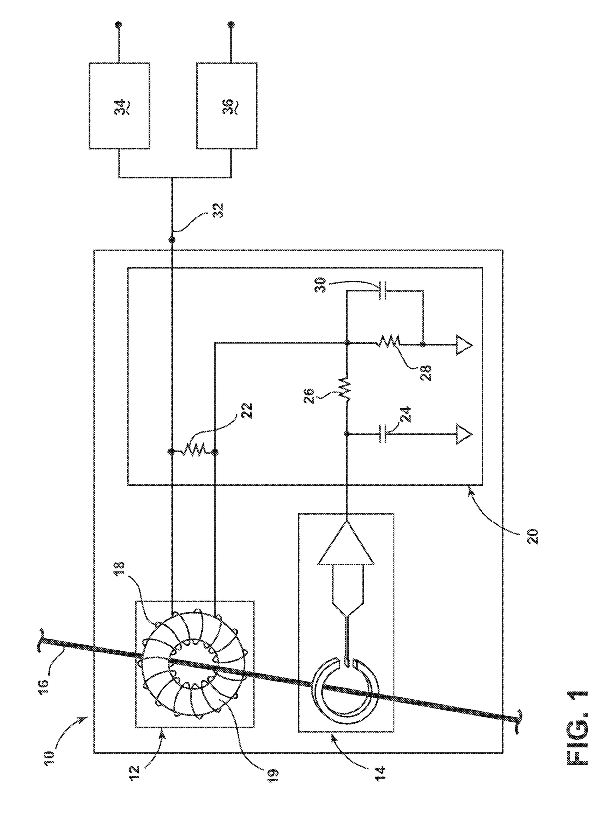
[0007]Consequently, where wide bandwidth current sensing is required for control and fault detection, there is a need for such a composite current sensor.

[0008]In the background and the following description, for the purposes of explanation, numerous specific details are set forth in order to provide a thorough understanding of the technology described herein. It will be evident to one skilled in the art, however, that the exemplary embodiments may be practiced without these specific details. In other instances, structures and devices are shown in diagram form in order to facilitate description of the exemplary embodiments.

[0009]The exemplary embodiments are described with reference to the drawings. These drawings illustrate certain details of specific embodiments that implement a module, method, or computer program product described herein. However, the drawings should not be construed as imposing any limitations that may be present in the drawings.

[0010]Technical effects of the me...


PUM


Abstract

A device for measuring electrical current in a line may include, among other things, a Hall effect sensor wherein a first response is generated by electrical current in the line; a current transformer disposed with the line extending axially therethrough and connected in series to the Hall effect sensor wherein a second response is generated by the electrical current in the line. An equalizer may be connected to the Hall effect sensor and to the current transformer and may be configured to flatten the first and second responses relative to each other. The permeability magnetic path length and cross section of the current transformer is selected such that low frequency roll-off of the current transformer is at a lower frequency than high frequency roll-off of the Hall effect sensor.

Description

BACKGROUND OF THE INVENTION[0001]Due, in part, to the advent of silicon carbide (SiC) metal-oxide-semiconductor (MOS) devices, solid-state power switches for power conversion and distribution systems can switch significant levels of power in a relatively short time in comparison to silicon based semiconductors and electromechanical devices. In applications where the load power consists of low frequency alternating current (AC) or direct current (DC), Hall effect devices or resistive sensing are needed. At higher power levels resistive sensing is problematic due to power dissipation or sensing very small voltages and Hall effect sensors typically have inadequate bandwidth. This leads to poor control system bandwidth and the potential for damage under fault conditions.BRIEF DESCRIPTION OF THE INVENTION[0002]One aspect of the invention relates to a device for providing a wide bandwidth current sensing measurement. The device for measuring electrical current in a line includes: a Hall e...

Claims


Application Information

Patent Timeline
Patent Type & Authority Patents(United States)
IPC IPC(8): G01R33/06G01R15/18G01R15/20
CPCG01R15/207G01R15/18G01R15/202
Inventor EPPS, PHILIP HENRY RICHARDCOLE, ANDREW BENJAMINHADZIBABIC, PREDRAG
Owner GE AVIATION SYST LLC
Why Eureka
Try Eureka