
Exhaust pipe mounting unit for vehicle

a technology for exhaust pipes and mounting units, which is applied in the direction of machines/engines, transportation and packaging, machine supports, etc., can solve the problems of affecting the stability of the hanger rubber of the rubber material, and affecting the comfort of the vehicle, so as to reduce the contact noise, the effect of more stably connecting to the vehicle body and reducing the contact nois

Active Publication Date: 2017-03-28
HYUNDAI MOTOR CO LTD
View PDF24 Cites 5 Cited by
  • Summary
  • Abstract
  • Description
  • Claims
  • Application Information

AI Technical Summary

Benefits of technology

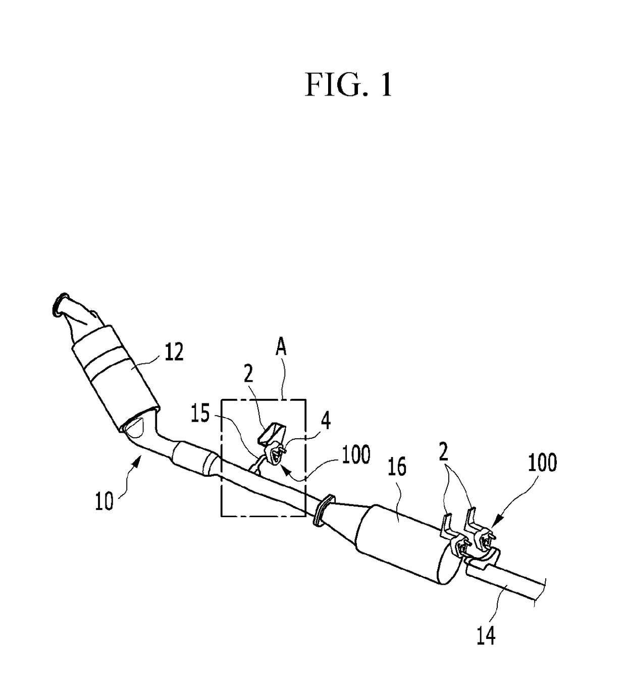
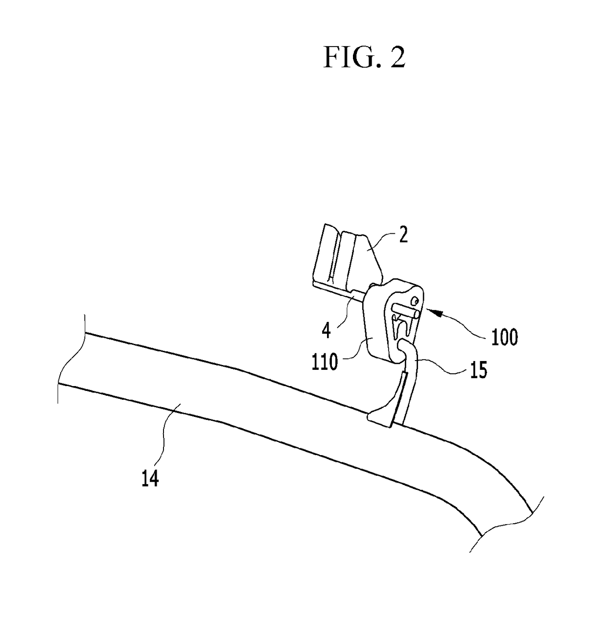
[0009]The present invention provides an exhaust pipe mounting unit for a vehicle capable of more stably coupling an exhaust pipe to a vehicle body and reduces the occurrence of contact noise upon translation of the exhaust pipe.
[0013]As described above, by an exhaust pipe mounting unit for a vehicle according to an exemplary embodiment of the present invention, an exhaust pipe may be more stably connected to a vehicle body. When the exhaust pipe translates, by enabling a lubricant to be supplied between a hanger rod of the exhaust pipe, contact noise may be reduced. Further, by the reduction of the contact noise from occurring between the hanger rod of the exhaust pipe and an exhaust pipe mounting unit, ride comfort of a vehicle may be improved. In addition, by reducing (e g, minimizing) a friction from occurring between the exhaust pipe mounting unit and the hanger rod, durability of the exhaust pipe mounting unit may be improved.

Problems solved by technology

However, as described above, in the conventional hanger rubber, at a contact surface in which the hanger rod is mounted, contact noise occurs when a vibration occurs in the exhaust pipe.
Further, the durability of the hanger rubber of a rubber material deteriorates due to frequent friction with the hanger rod.
Contact noise is simultaneously transferred to the vehicle body, which compromises the comfort of the vehicle.

Method used


Image

  • Exhaust pipe mounting unit for vehicle
  • Exhaust pipe mounting unit for vehicle
  • Exhaust pipe mounting unit for vehicle

Examples


Embodiment Construction

[0030]An exemplary embodiment of the present invention will hereinafter be described in detail with reference to the accompanying drawings.

[0031]An exemplary embodiment described in this specification and a configuration shown in the drawing is merely an exemplary embodiment of the present invention and do not represent an entire technical idea of the present invention and thus it should be understood that various equivalents and exemplary variations that can replace the exemplary embodiment may exist at an application time point of the present invention. On the contrary, the invention is intended to cover not only the exemplary embodiments, but also various alternatives, modifications, equivalents and other embodiments, which may be included within the spirit and scope of the invention as defined by the appended claims.

[0032]The drawings and description are to be regarded as illustrative in nature and not restrictive. Like reference numerals designate like elements throughout the s...


PUM


Abstract

An exhaust pipe mounting unit for a vehicle is provided. The exhaust pipe mounting unit includes a main body that has an operation aperture formed at the center thereof and a connection aperture that is formed at a first side in a length direction of the main body to couple a connection load of a bracket mounted in a lower portion of a vehicle body. A mounting aperture is formed at a second side in a length direction of the main body to connect a hanger rod disposed in an exhaust pipe. A chamber is formed in a lower portion of the interior of the main body to be connected to an internal circumferential surface of the mounting aperture and a lubricant is filled therein. Further a piston within the chamber selectively supplies a lubricant filled in the chamber to an internal circumferential surface of the mounting aperture, upon translation of the exhaust pipe.

Description

CROSS-REFERENCE TO RELATED APPLICATION[0001]This application claims priority to and the benefit of Korean Patent Application No. 10-2015-0130421 filed in the Korean Intellectual Property Office on Sep. 15, 2015, the entire contents of which are incorporated herein by reference.BACKGROUND[0002](a) Field of the Invention[0003]The present invention relates to an exhaust pipe mounting unit for a vehicle and more particularly, to an exhaust pipe mounting unit for a vehicle that connects an exhaust pipe to a vehicle body and that prevents contact noise from occurring upon translation of the exhaust Pipe.[0004](b) Description of the Related Art[0005]Generally, exhaust gas in an engine of a vehicle after combustion is discharged to the air through an exhaust assembly. For example, the exhaust assembly includes a plurality of exhaust pipes that are connected to an exhaust manifold of the engine and that are connected from a lower portion of a vehicle body to the rear side of the vehicle. Fur...

Claims


Application Information

Patent Timeline
Patent Type & Authority Patents(United States)
IPC IPC(8): F16M13/00F01N13/18
CPCF01N13/1822B60K13/04F01N13/08F01N13/16
Inventor LEE, SANGHO
Owner HYUNDAI MOTOR CO LTD
Learn More