
Air cleaner apparatus for vehicle and mold unit for fabricating the same

a mold unit and air cleaner technology, applied in the direction of combustion-air/fuel-air treatment, separation process, filtration separation, etc., can solve the problems of difficult to ensure dimensional stability against deformation, engine damage, and inability to form sealing structures, etc., to increase the strength of the body, and ensure the effect of dimensional stability

Active Publication Date: 2017-03-21
HYUNDAI MOTOR CO LTD +1
View PDF22 Cites 4 Cited by
  • Summary
  • Abstract
  • Description
  • Claims
  • Application Information

AI Technical Summary

Benefits of technology

The present invention is about an air cleaner for a vehicle that has a stronger design for better performance and noise, vibration, and harshness (NVH) reduction. The invention features an integrated reinforcement structure, a seal structure, and additional reinforcement ribs for the body. The driving member includes cam shafts and bevel gears for easy storage and maintenance of the filter. This design also allows for the formation of horizontal ribs using sliding molds, resulting in a stronger body with improved NVH performance. Overall, the invention provides an improved design for the air cleaner that increases its strength and reduces its size and noise.

Problems solved by technology

When impurities are introduced into an engine, the engine may be damaged due to abnormal combustion or trouble in the engine, which are problematic.
When the vibration energy is transmitted to the workpieces through the tool horn, strong vibration generates frictional heat such that welding and bonding occurs at bonding surfaces of the workpieces.
After the welding process of the cover and the body, it is difficult to ensure dimensional stability against deformation.
When the welding surface is formed at a lower position in order to overcome this problem, a sufficient space is not obtained, and thus a sealing structure is not formed, which is problematic.

Method used


Image

  • Air cleaner apparatus for vehicle and mold unit for fabricating the same
  • Air cleaner apparatus for vehicle and mold unit for fabricating the same
  • Air cleaner apparatus for vehicle and mold unit for fabricating the same

Examples


Embodiment Construction

[0033]Reference will now be made in detail to various embodiments of the present invention(s), examples of which are illustrated in the accompanying drawings and described below. While the invention(s) will be described in conjunction with exemplary embodiments, it will be understood that the present description is not intended to limit the invention(s) to those exemplary embodiments. On the contrary, the invention(s) is / are intended to cover not only the exemplary embodiments, but also various alternatives, modifications, equivalents and other embodiments, which may be included within the spirit and scope of the invention as defined by the appended claims.

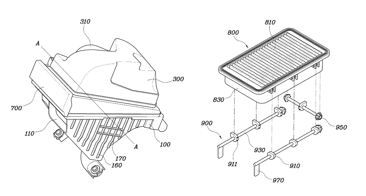
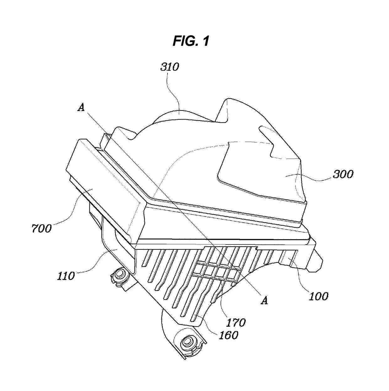
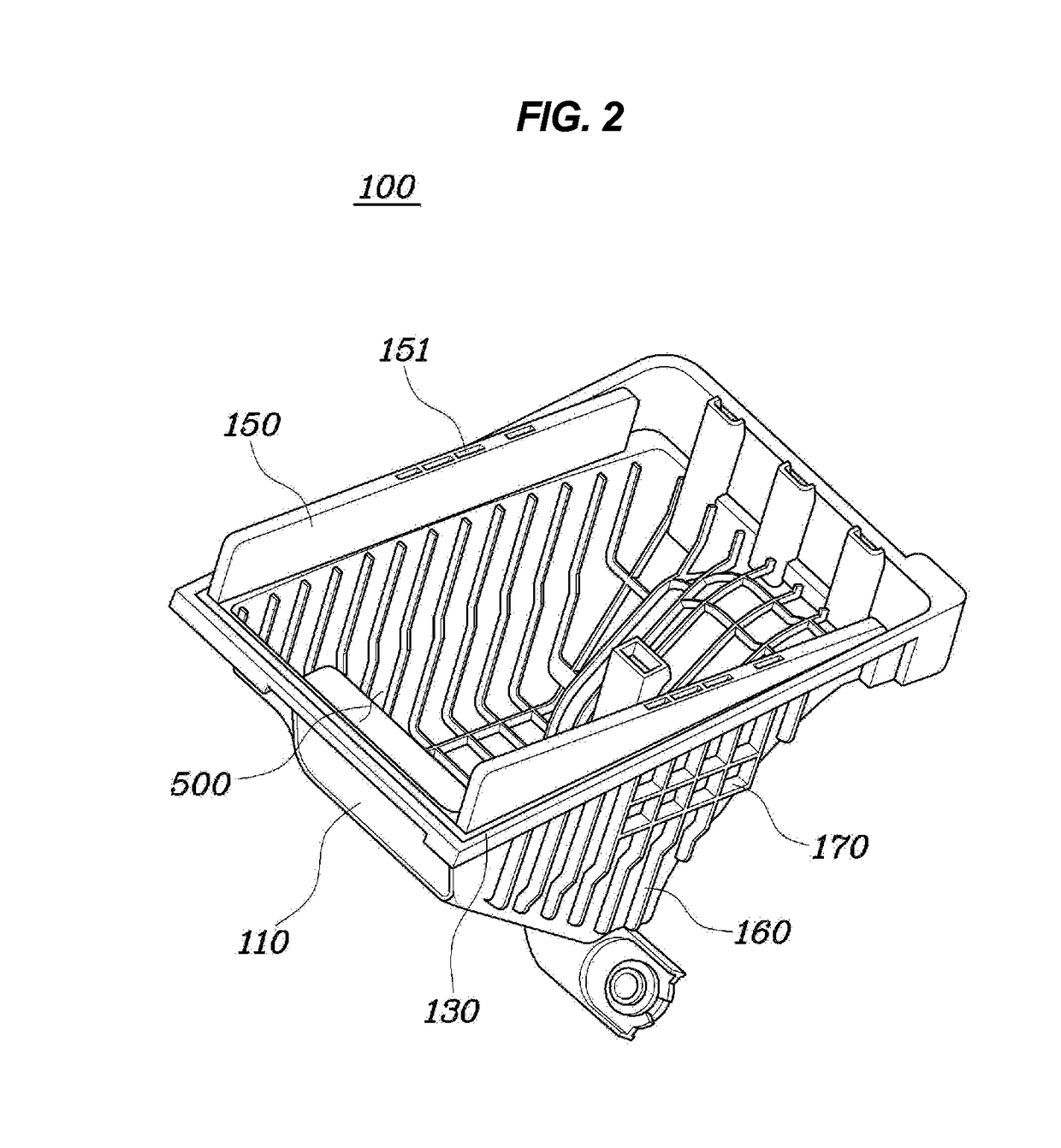
[0034]FIG. 1 is a perspective view showing an air cleaner for a vehicle according to an exemplary embodiment of the present invention, FIG. 2 is a perspective view showing a body 100 of the air cleaner shown in FIG. 1, and FIG. 3 is a cross-sectional view taken along line A-A in FIG. 1. FIG. 4 is a view showing a mold unit 200, 40...


PUM

PropertyMeasurementUnit
thicknessaaaaaaaaaa
distancesaaaaaaaaaa
lengthaaaaaaaaaa

Abstract

An air cleaner apparatus for a vehicle includes a body defining therein a storage space. The body has an intake port through which air is to be taken in, a laterally-bent support section disposed at an upper portion, and plate-shaped reinforcement members disposed above the storage space and having a predetermined thickness, wherein a cover is coupled to the upper portion of the body, defines therein a storage space, and has a discharge port at one side through which air is to be discharged and a laterally-bent coupling section disposed at a lower side, wherein an opening is provided at front sides of the body and cover, and serves as an entrance through which a filter member is stored or taken out, and wherein a plate-shaped cover is coupled to a front portion of the storage part in order to open or close the storage part.

Description

CROSS-REFERENCE TO RELATED APPLICATION[0001]The present application claims priority of Korean Patent Application Number 10-2014-0041915 filed on Apr. 8, 2014, the entire contents of which application are incorporated herein for all purposes by this reference.BACKGROUND OF THE INVENTION[0002]Field of the Invention[0003]The present invention relates, in general, to an air cleaner apparatus for a vehicle and a mold unit for fabricating the same and, more particularly, to an air cleaner for a vehicle and a mold unit for fabricating the same, in which the airtightness and strength of a case of the air cleaner is increased to reduce noise emission while the vehicle is being driven, thereby improving noise, vibration and harshness (NVH) performance.[0004]Description of Related Art[0005]Typically, an intake system of a vehicle takes in external air, which is used for combustion. When impurities are introduced into an engine, the engine may be damaged due to abnormal combustion or trouble in...

Claims


Application Information

Patent Timeline
Patent Type & Authority Patents(United States)
IPC IPC(8): F02M35/02F02M35/024B29C33/42B29C45/44B29C45/37B29C45/33
CPCF02M35/0201F02M35/0202F02M35/0203F02M35/02416F02M35/02491B29C33/42B29C45/33B29C45/37B29C45/44B01D27/02B01D46/00F02M35/024F02M35/10
Inventor CHO, YOON GEUN
Owner HYUNDAI MOTOR CO LTD
Learn More