Visible X-ray indication and detection system for X-ray backscatter applications

a detection system and backscatter technology, applied in the field of backscattered x-rays, can solve the problems of difficult detection without using expensive, advanced equipment, and quantitative characterizing a flux of x-rays usually requires expensive, advanced equipmen

Active Publication Date: 2017-03-14
THE BOEING CO
View PDF46 Cites 5 Cited by
  • Summary
  • Abstract
  • Description
  • Claims
  • Application Information

AI Technical Summary

Problems solved by technology

However, because X-rays are so energetic, they are difficult to detect without using expensive, advanced equipment.
Similarly, quantitatively characterizing a flux of X-rays usually requires expensive, advanced equipment.

Method used


Image

  • Visible X-ray indication and detection system for X-ray backscatter applications
  • Visible X-ray indication and detection system for X-ray backscatter applications
  • Visible X-ray indication and detection system for X-ray backscatter applications

Examples


Embodiment Construction

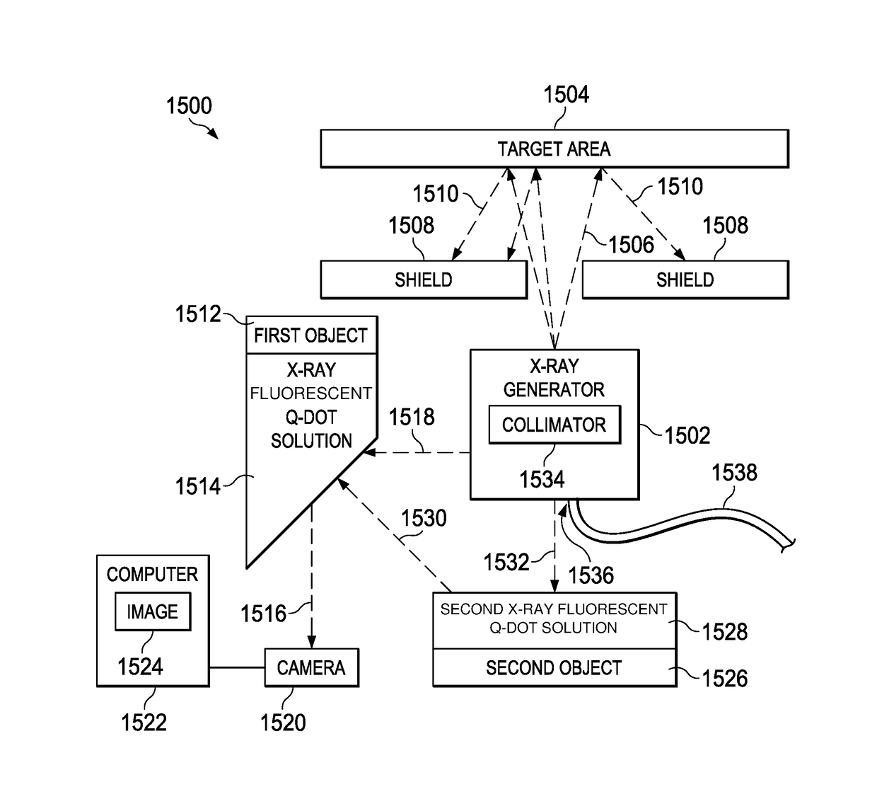
[0032]The illustrative embodiments provide several useful functions. For example, the illustrative embodiments recognize and take into account that inexpensively detecting X-rays, including backscattered X-rays, remains challenging. The illustrative embodiments also recognize and take into account that a mechanism for detecting the presence of X-rays with an indicator in the visible spectrum of light would allow for rapid reaction to the presence of X-rays. The illustrative embodiments also recognize and take into account that the presence and distribution of X-rays indicated using visible light will allow ordinary visible light cameras to guide and control X-ray related equipment, including X-ray generators, X-ray targets, X-ray monitors, and the like.

[0033]As used herein, “X-rays”, like visible light, are photons, a form of electromagnetic radiation. X-rays have a wavelength in the range of about 0.01 nanometers to about 10 nanometers, corresponding to frequencies in the range of ...


PUM

PropertyMeasurementUnit
frequenciesaaaaaaaaaa
areaaaaaaaaaaa
fluorescentaaaaaaaaaa

Abstract

An X-ray backscatter indication and detection system, including an object disposed with respect to a target area targeted by X-rays, such that X-rays that backscatter from the target area strike the surface of the object. The surface of the object includes an X-ray sensitive indicator substance that fluoresces with a visible light when contacted by backscattered X-rays.

Description

BACKGROUND INFORMATION[0001]1. Field[0002]The present disclosure relates to the indication, detection and characterization of X-rays, and more particularly to backscattered X-rays.[0003]2. Background[0004]X-rays are an energetic form of light the human eye cannot see. As is well known, X-rays have many useful applications, such as in medicine, dentistry, and scientific research.[0005]However, because X-rays are so energetic, they are difficult to detect without using expensive, advanced equipment. Similarly, quantitatively characterizing a flux of X-rays usually requires expensive, advanced equipment. Thus, new and improved techniques for detecting and characterizing X-rays are desirable, particularly for backscattered X-rays. Backscattered X-rays are X-rays that strike a target area and then scatter from the target area, potentially striking one or more additional areas other than the target.SUMMARY[0006]The illustrative embodiments provide for a number of different implementations...

Claims


Application Information

Patent Timeline
Patent Type & Authority Patents(United States)
IPC IPC(8): G01N23/203G01T1/16G01T1/04G01N23/207G01T1/20G01T1/10
CPCG01N23/203G01N23/2076G01T1/04G01T1/10G01T1/16G01T1/20G01T7/00G01V5/0016G01V5/0025G01N23/223G01N2223/053G01N2223/0766G01N2223/32
Inventor GEORGESON, GARY E.
Owner THE BOEING CO
Why Eureka
Try Eureka