
Electric kick scooter

a kick scooter and electric technology, applied in the field of electric kick scooters, can solve the problems of not every user can handle skillfully, user would spend considerable physical strength to drive the kick scooter forward, and increase the risk of use, so as to facilitate users to control the speed of the scooter, and the effect of well-being of manipulation

Active Publication Date: 2017-02-28
J D COMPONENTS CO LTD
View PDF11 Cites 3 Cited by
  • Summary
  • Abstract
  • Description
  • Claims
  • Application Information

AI Technical Summary

Benefits of technology

The present invention is an electric kick scooter that makes it easy for users to control how they accelerate, decelerate, and brake. The scooter is designed to be safe and easy to use.

Problems solved by technology

Nevertheless, when riding on an uphill path, in addition to the decrease of gliding speed of the kick scooter, the user would spend considerable physical strength to drive the kick scooter forward.
However, whichever way of driving is used, certain coordination is needed in manipulation, and thus not every user can handle skillfully.
Furthermore, once an emergency situation that deceleration braking is needed is encountered, the user often cannot appropriately react to the grip or food plate immediately, thereby imperceptibly increasing the risk in use.

Method used


Image

  • Electric kick scooter
  • Electric kick scooter
  • Electric kick scooter

Examples


Embodiment Construction

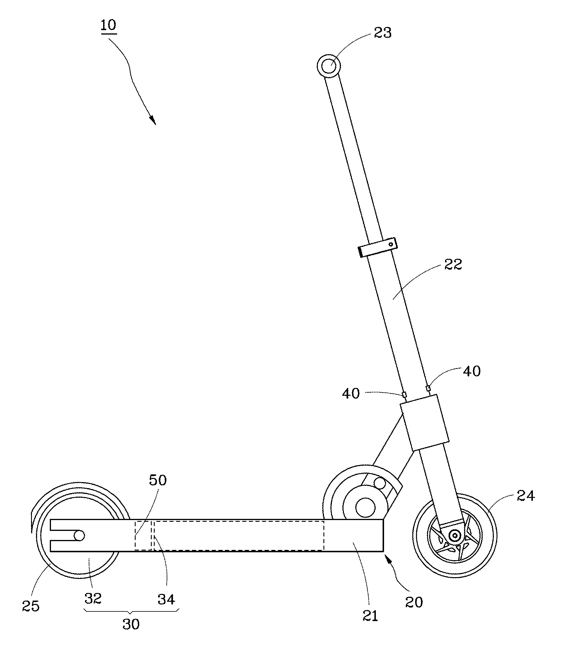
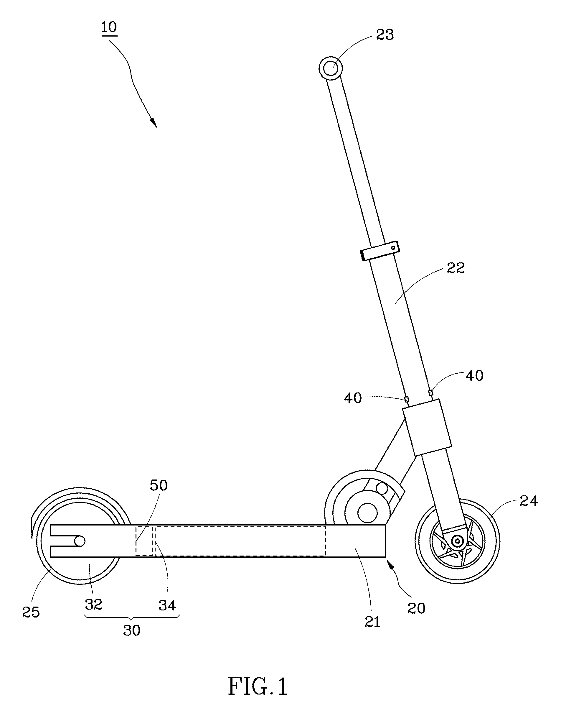
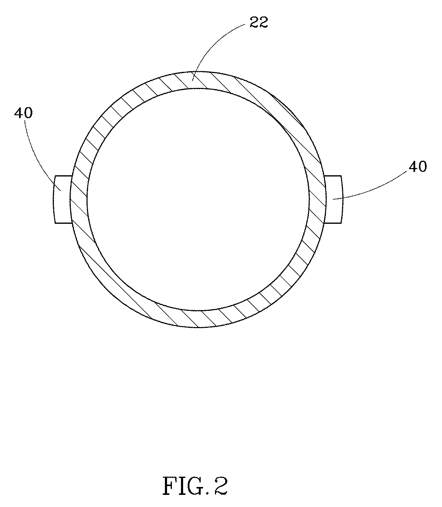
[0016]First referring to FIG. 1, an electric kick scooter 10 of a first embodiment of the present invention comprises a scooter body 20, a drive device 30, two strain gauges 40 and a controller 50.

[0017]The scooter body 20 has a foot plate 21, a steering tube 22, a handle bar 23, a front wheel 24 and a rear wheel 25. The steering tube 22 is installed at a frond end of the foot plate 21, and the handle bar 23 is installed at a top end of the steering tube 22 for a user to grasp so as to manipulate turning left and right, pushing forward and pulling backward with respect to the steering tube 22, The front wheel 24 is rotatably installed at a bottom end of the steering tube 22, and the rear wheel 25 is rotatably installed at a rear end of the foot plate 21.

[0018]With reference to FIGS. 1 and 3, the drive device 30 has a motor 32 and a battery 34. The motor 32 may be installed in the front wheel 24 or rear wheel 25 of the scooter body 20. In this embodiment, the motor 32 is installed in...


PUM


Abstract

An electric kick scooter including a scooter body, a drive device and a strain gauge is provided. The scooter body has a foot plate, a steering tube and a rear wheel respectively provided at front and rear ends of the foot plate, and a handle bar and a front wheel respectively provided at top and bottom ends of the steering tube. The drive device has a motor installed in the front wheel or rear wheel, and a battery installed with the scooter body and electrically connected to the motor. The strain gauge is attached to the steering tube or handle bar of the scooter body to sense the strain generated on the steering tube or handle bar when it receives a force. The strain signal of the strain gauge is transmitted to a controller for enabling the controller to control an action of the motor accordingly.

Description

CROSS-REFERENCE TO RELATED APPLICATIONS[0001]This application claims priority from Taiwan Patent Application No. 102104047 filed on Feb. 1, 2013, the entire content of which is incorporated herein by reference.BACKGROUND OF THE INVENTION[0002]1. Field of the Invention[0003]The present invention relates to an electric kick scooter, and particularly to an electric kick scooter with the convenience of manipulation.[0004]2. Description of the Related Art[0005]A traditional kick scooter is propelled by a user stepping continuously on the ground with a single foot to achieve an effect of gliding forward. Nevertheless, when riding on an uphill path, in addition to the decrease of gliding speed of the kick scooter, the user would spend considerable physical strength to drive the kick scooter forward. So this will greatly reduce the user's interest to the kick scooter. Accordingly, to reduce the influence of uphill sections on the interest of user of kick scooters, there are currently so-cal...

Claims


Application Information

Patent Timeline
Patent Type & Authority Patents(United States)
IPC IPC(8): A63C17/12B62M6/50B62M6/40B62K3/00B62K23/00
CPCB62M6/40B62K3/002B62K23/00B62M6/50
Inventor HSU, YUAN-FANG
Owner J D COMPONENTS CO LTD
Learn More