Flexible impact protection
a technology of flexible impact protection and tensile connection, which is applied in the direction of vehicular safety arrangements, pedestrian/occupant safety arrangements, vehicle components, etc., can solve the problems of injuring the rider or passenger of the vehicle, injuring the person if, and injuring the person, so as to increase the stiffness of the flexible impact protection member, increase the tension, and increase the effect of the tensile connection
- Summary
- Abstract
- Description
- Claims
- Application Information
AI Technical Summary
Benefits of technology
Problems solved by technology
Method used
Image

Examples
first embodiment
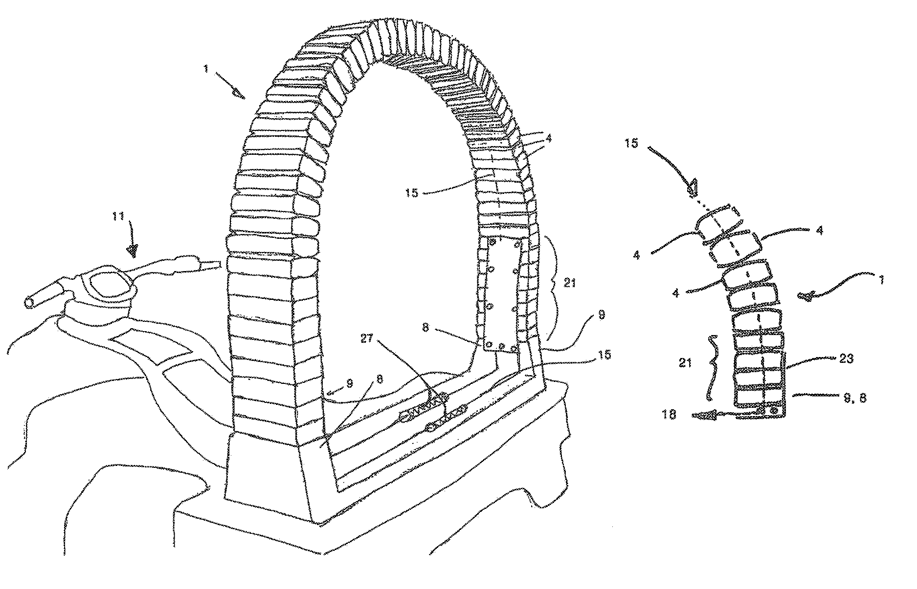
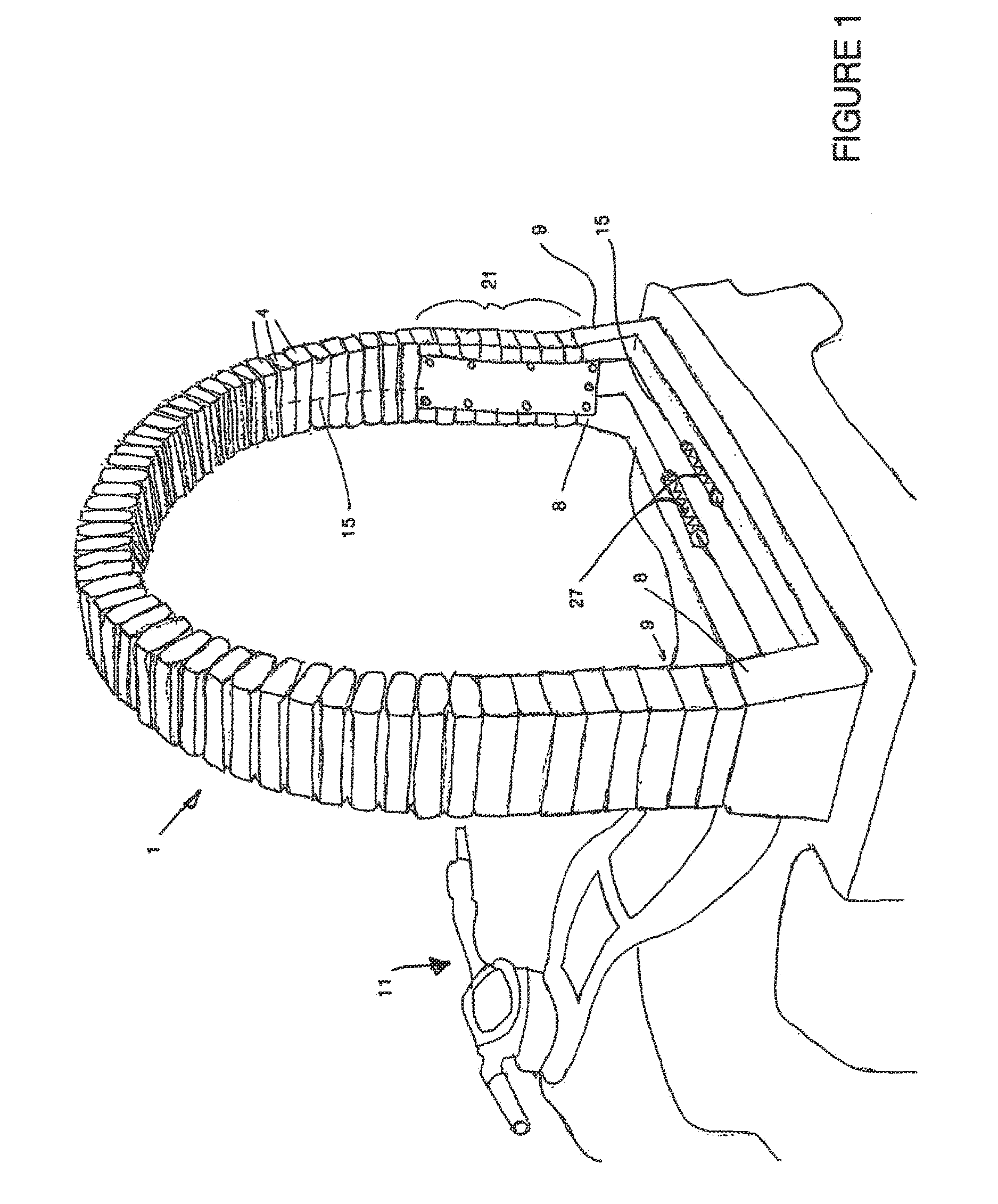
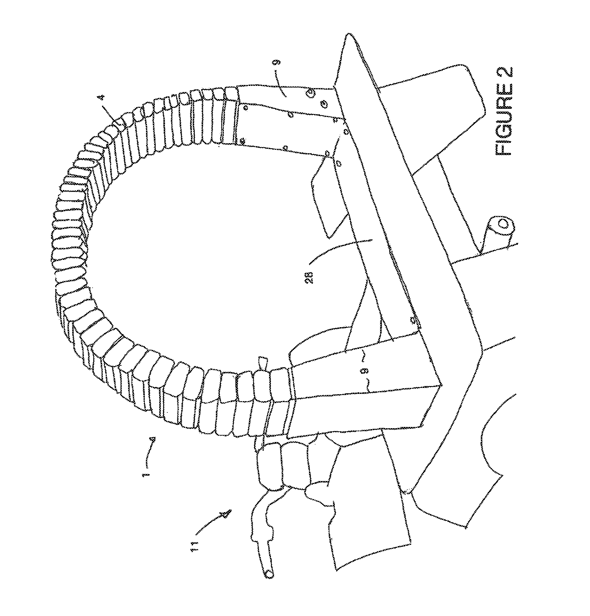
[0131]the invention is described with references to FIGS. 1 through 11 shown attached to a vehicle 11. The flexible impact protection member 1 comprises a number of mobile portions 4 shown in FIGS. 3 and 4. In the preferred embodiment these are joined end on end as shown to form a member 1. In the embodiment shown such as in FIG. 1 this is a hoop shaped arrangement with ends 9. However other arrangements may also be formed such as a straight member, or continuous as the situation requires. As can be seen the member 1 when in a hoop or closed form is largely flat and thus has a major plane 7 (the plane of the page in FIGS. 4, 5A and B). The member 1 is substantially rigid to movement out of this plane but is disposed to flex in response to an impact 6 in the line of parallel to the plane 7, as shown in FIG. 5. The member is therefore arranged when fixed to the first member 2 so as to receive the majority of expected impact events in the line of the major plane 7. The member may be at...
second embodiment
[0145]A second embodiment will now be described with reference to FIGS. 13 through 16 and 19. The flexible impact protection member 1 shown utilises fewer mobile portions and may only use one 4. This may take the form of a hollow member 32 through which one or more tensile connections 5 pass. In the preferred form these are flexible tensile members as previously outlined. The mobile portion 4 and tensile connections then connect to ends 9 which can then be attached to the member requiring protection. Again the member 1 lies substantially in a major plane 7 and is more resilient to out of plane flex than in plane flex. Again the member would be aligned so as to receive the majority of impact events in the major plane. The ends 9 are braced as shown so as to increase stiffness to out of place movement 33. There may optionally be tensile connections in these regions also. Such movement 33 would tension that edge 34 which an impact event 6 would deflect the member 1 away from. The outsi...
PUM
| Property | Measurement | Unit |
|---|---|---|
| flexible | aaaaa | aaaaa |
| tensile force | aaaaa | aaaaa |
| tension | aaaaa | aaaaa |
Abstract
Description
Claims
Application Information
 - R&D
- Intellectual Property
- Life Sciences
- Materials
- Tech Scout
- Unparalleled Data Quality
- Higher Quality Content
- 60% Fewer Hallucinations
Browse by: Latest US Patents, China's latest patents, Technical Efficacy Thesaurus, Application Domain, Technology Topic, Popular Technical Reports.
© 2025 PatSnap. All rights reserved.Legal|Privacy policy|Modern Slavery Act Transparency Statement|Sitemap|About US| Contact US: help@patsnap.com