
Magnetic plate used for rotor core of motor and method for manufacturing magnetic plate

a technology of magnetic plate and rotor core, which is applied in the direction of magnetic circuit rotating parts, dynamo-electric machines, and shape/form/construction of magnetic circuits, etc. it can solve the problemslimiting the improvement of output density, and reducing the centrifugal strength. , to achieve the effect of reducing the maximum number of rotations, reducing the radial width of the magnetic pole portion, and reducing the centri

Inactive Publication Date: 2017-02-14
NHK SPRING CO LTD
View PDF18 Cites 0 Cited by
  • Summary
  • Abstract
  • Description
  • Claims
  • Application Information

AI Technical Summary

Benefits of technology

[0018]A problem to be solved is that: the reduction in the radial width of the magnetic pole portion for higher torque is likely to cause plastic deformation at the end corner portions of the opening on which the stress concentration is generated based on the centrifugal force of the permanent magnet at the time of the rotation, reduces the centrifugal strength, and lowers the maximum number of rotation capable of resisting the centrifugal force, and this results in a limit on improvement of the output density and on downsizing; in the vicinity of the end portion of the opening, ineffective magnetic flux is formed so as not to contribute to the rotation torque of the rotor; and in the rotor incorporating the permanent magnet having the rectangular cross-section, the magnetic flux distribution caused on the outer peripheral surface becomes the rectangular wave shape including the many higher harmonic waves to increase iron loss.
[0019]The present invention, in order to be able to contribute to higher torque density, higher output density, and downsizing and prevent ineffective magnetic field and higher harmonic waves, provides a magnetic plate used for a rotor core of a motor, the magnetic plate having a body portion formed into an annular shape, the rotor core in which a plurality of the magnetic plates are stacked one on another and permanent magnets whose cross-section is approximately rectangular and is elongated in a circumferential direction of the body portion are held by a plurality of openings being formed so as to be elongated in the circumferential direction inside an outer peripheral edge and being arranged at a predetermined interval in the circumferential direction. The magnetic plate includes a magnetic pole portion being set between the outer peripheral edge of the body portion and the opening and having a radial width being set so as to be smaller than a rotor radial width (length of a short side. Hereinafter referred to as a radial sectional width of the permanent magnet) in a cross-section of the permanent magnet, and a higher hardness portion being set to be formed into a hook shape along an end corner of the opening and have a radial maximum width being a smaller width than the radial sectional width of the permanent magnet.
[0020]The magnetic plate of the present invention, because of the aforementioned configuration, allows a width of a portion spanning from the higher hardness portion being formed into the hook shape along the end corner of the opening to the magnetic pole portion to be set to be smaller than the radial sectional width of the permanent magnet, thereby to reduce magnetic resistance at the magnetic pole portion. The higher hardness portion being formed into the hook shape along the end corner of the opening improves centrifugal strength (resistance to plastic deformation) of the opening, prevents and activates ineffective magnetic flux that does not contribute to rotor rotation torque around the end corner of the opening, and prevent higher harmonic waves included in magnetic flux distribution generated on an outer peripheral surface of the rotor by the permanent magnet having the rectangular cross section.
[0021]Therefore, it contributes to higher torque, higher output and downsizing etc, required for industrial motors, electric vehicles and hybrid vehicles etc.

Problems solved by technology

A problem to be solved is that: the reduction in the radial width of the magnetic pole portion for higher torque is likely to cause plastic deformation at the end corner portions of the opening on which the stress concentration is generated based on the centrifugal force of the permanent magnet at the time of the rotation, reduces the centrifugal strength, and lowers the maximum number of rotation capable of resisting the centrifugal force, and this results in a limit on improvement of the output density and on downsizing; in the vicinity of the end portion of the opening, ineffective magnetic flux is formed so as not to contribute to the rotation torque of the rotor; and in the rotor incorporating the permanent magnet having the rectangular cross-section, the magnetic flux distribution caused on the outer peripheral surface becomes the rectangular wave shape including the many higher harmonic waves to increase iron loss.

Method used


Image

  • Magnetic plate used for rotor core of motor and method for manufacturing magnetic plate
  • Magnetic plate used for rotor core of motor and method for manufacturing magnetic plate
  • Magnetic plate used for rotor core of motor and method for manufacturing magnetic plate

Examples


embodiment 1

Shape Example 1

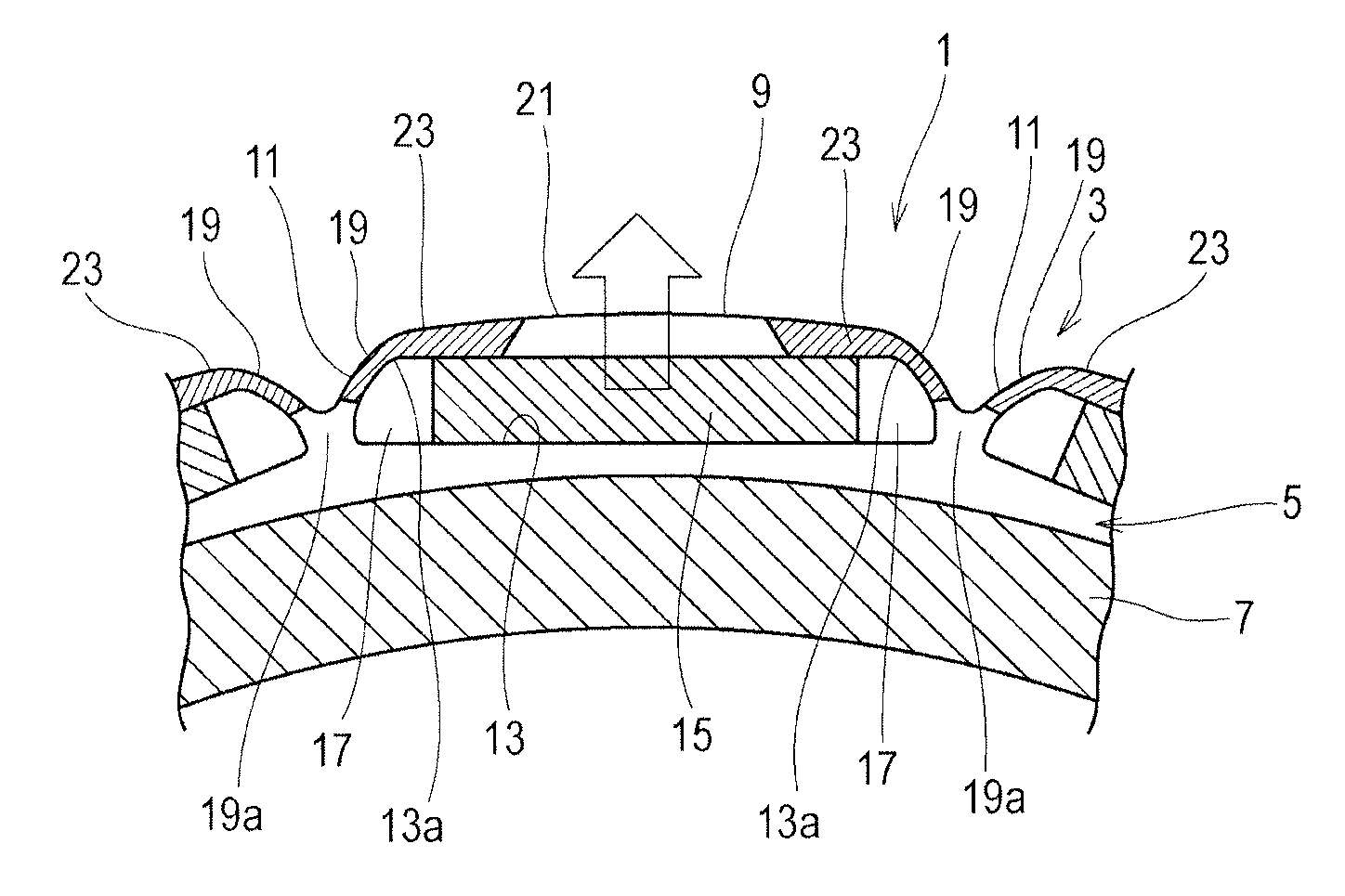
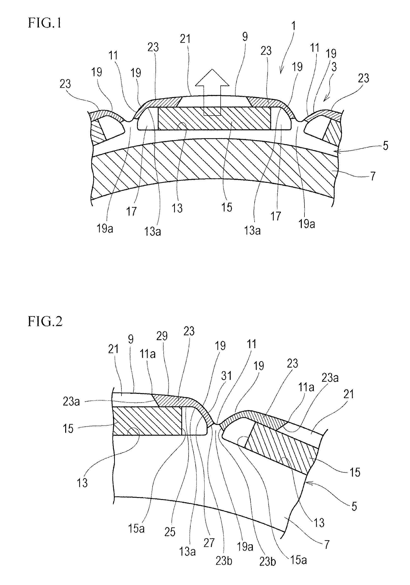
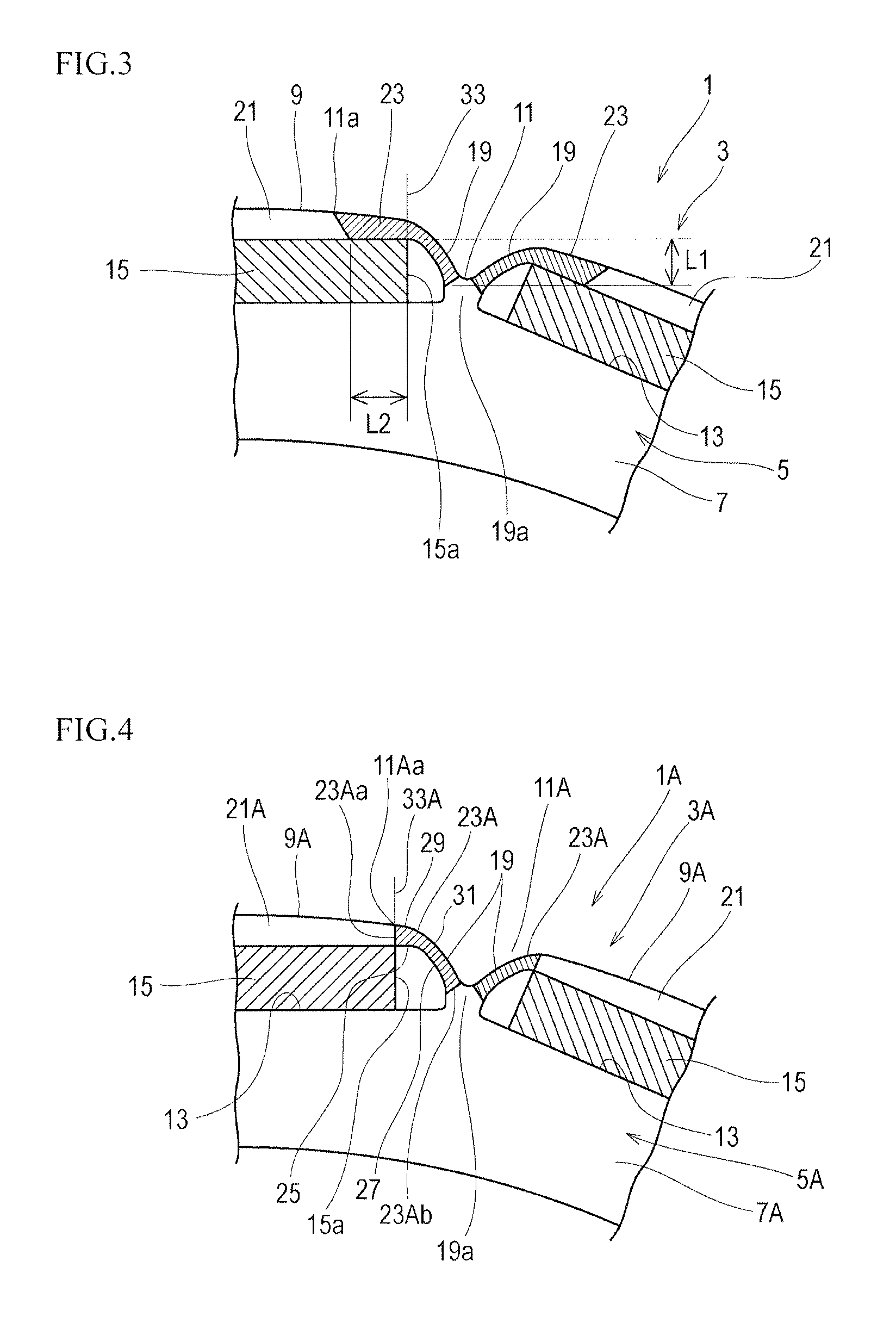
[0058]FIG. 1 is a partial front view of a rotor (a front face with respect to a magnetic plate face), FIG. 2 is a partial front view of the rotor at a shifted rotational position, and FIG. 3 is a partial front view illustrating a dimensional relationship. In addition, FIG. 1 is also used for explanation of a method of evaluating centrifugal strength mentioned later and therefore also illustrates hatching of a fixed portion and an arrow of a loading direction.

[0059]As illustrated in FIGS. 1 and 2, the rotor core 3 of the rotor 1 used for an electric motor is formed by stacking a plurality of the magnetic plates 5. Each magnetic plate 5 has the body portion 7 that is formed using material with high magnetic permeability such as silicon steel sheet in an annular shape such as disk or ring. The silicon steel sheet composing the body portion 7 has the compositions (percentage by mass) of Si: 2 to 4 and the reminder: iron and unavoidable impurities. Meanwhile, other materia...

example 2

Shape Example 2

[0076]FIG. 4 is a partial front view of a rotor corresponding to FIGS. 2 and 3. The same components as the shape example 1 are represented with the same reference numerals and corresponding components are represented with the same reference, numerals with “A”, to avoid repetition in a description.

[0077]In the magnetic plate 5A according to the shape example 2 of the embodiment 1, the extent of the higher hardness portion 23A in the circumferential direction of the body portion 7 is set up to the boundary 33A that straightly leads along the end edge 15a of the permanent magnet 15 to the outer peripheral edge 9A. The end edge 23Aa of the higher hardness portion 23A in the circumferential direction of the body portion 7A is positioned onto the boundary 33A. In this shape example 2, the end edge 23Aa and the starting point 11Aa of the recessed portion 11A are positioned onto the boundary 33A. L2=0 is concluded.

[0078]The others are the same as the shape example 1.

example 3

Shape Example 3

[0079]FIG. 5 is a partial front view of a rotor corresponding to FIGS. 2 and 3. The same components as the shape example 1 are represented with the same reference numerals and corresponding components are represented with the same reference numerals with “B”, to avoid repetition in a description.

[0080]In the magnetic plate 5B according to the shape example 3 of the embodiment 1, the extent of the higher hardness portion 23B in the circumferential direction of the body portion 7B is set so as to exceed the boundary 33B that leads along the end edge 15a of the permanent magnet 13 to the outer peripheral edge 9B and enter the center side of the magnetic pole portion 21. The end edge 23Ba of the higher hardness portion 23B in the circumferential direction of the body portion 7 is set in parallel with the boundary 33B.

[0081]The others are the same as the shape example 1.


PUM


Abstract

A magnet plate used for a rotor core of a motor, includes a magnetic pole portion being set between an outer peripheral edge of a body portion and a magnet slot and having a radial width being smaller than a radial sectional width of the permanent magnet, and a higher hardness portion being formed into a hook shape along an end corner of the magnet slot and have a smaller width than the radial sectional width of the permanent magnet.

Description

FIELD OF THE INVENTION[0001]The present invention relates to a magnetic plate used for a rotor core of a motor and a method for manufacturing the same.BACKGROUND OF THE INVENTION[0002]In recent years, in accordance with advances in new technology for a wide variety of electrical equipment, electric vehicles, hybrid vehicles, robots and the like, performance required for motors or electric generators used liar them becomes highly developed. For example, in industrial motors, electric vehicles, hybrid vehicles, or the like, there is a need for high torque, high output, space-saving and the like.[0003]Accordingly, there is a conventional rotor of a motor disclosed in Patent document 1 as illustrated in FIGS. 20 and 21. FIG. 20 is a perspective view illustrating the rotor and FIG. 21 is a conceptual view illustrating magnetic flux distribution.[0004]The rotor 101 includes a rotor core 105 in which a plurality of magnetic plates 103 having a circular shape as an annular shape are stacked...

Claims


Application Information

Patent Timeline
Patent Type & Authority Patents(United States)
IPC IPC(8): H02K1/27H02K15/03H02K29/03
CPCH02K1/276H02K15/03H02K1/27H02K1/2766H02K29/03
Inventor KAMEDA, YOHEIIWATA, KAZUOARAOKA, YUJIONO, YOSHIKI
Owner NHK SPRING CO LTD
Learn More