Counterweight arrangement for an elevator and an elevator

a technology for counterweights and elevators, which is applied in the direction of mine lifts, building lifts, transportation and packaging, etc., can solve the problems of complex cross beam shape, increased product cost, and difficulty in accessing the pulley for maintenan

Active Publication Date: 2017-02-07
KONE CORP
View PDF11 Cites 1 Cited by
  • Summary
  • Abstract
  • Description
  • Claims
  • Application Information

AI Technical Summary

Benefits of technology

[0003]The object of the invention is, inter alia, to solve one or more of the previously described drawbacks of known solutions and problems discussed later in the description of the invention. An object of the invention is, in particular, to provide an elevator and a counterweight arrangement thereof, which is simple in structure and less prone to twisting of the counterweight.
[0004]It is brought forward a new counterweight arrangement for an elevator, comprising a first vertical guide rail and a second vertical guide rail, said guide rails defining a vertical guide rail plane of the counterweight, a counterweight arranged to travel between the guide rails guided by said guide rails, the counterweight comprising a frame, which comprises a first upright beam and a second upright beam and a cross beam connecting the upper ends of the upright beams, and a diverting pulley mounted between the guide rails on the cross beam of the counterweight frame, the pulley having a vertical plane of rotation, which crosses the guide rail plane. The cross beam is aligned parallel with the plane of rotation of the pulley. With this kind of arrangement, a roping can be arranged to arrive and leave the pulley of the counterweight along a path that can be freely chosen irrespective of the guide rail plane. Therefore, the roping can be arranged to pass a path that is optimal for the elevator suspension or otherwise advantageous, for example so as to circumvent other elevator components. The cross beam being aligned parallel with the plane of rotation of the pulley reduces the twist of the counterweight frame. Thus, the counterweight behaves stably even though said planes cross each other. Said advantages are most clearly present when the angle of said crossing is less than thirty degrees.

Problems solved by technology

A problem in known arrangements has been that the shape of the cross beam has been complicated and due to the angle between the rotation plane and the cross structure additional stiffeners have been necessary.
Both the shape and number of parts adds to the cost of the product.
Also, the complicated structure has made it difficult to get access to the pulley for maintenance.
Additionally, it has been noticed that the different alignment of the cross beam of the frame and the pulley has causes that the frame tends to twist around a vertical axis and lean excessively on the guide rails via its guide members, such as the guide rollers or the guide sliders.
This twist has the drawback that it increases the noise level and wear of the guide members.

Method used


Image

  • Counterweight arrangement for an elevator and an elevator
  • Counterweight arrangement for an elevator and an elevator
  • Counterweight arrangement for an elevator and an elevator

Examples


Embodiment Construction

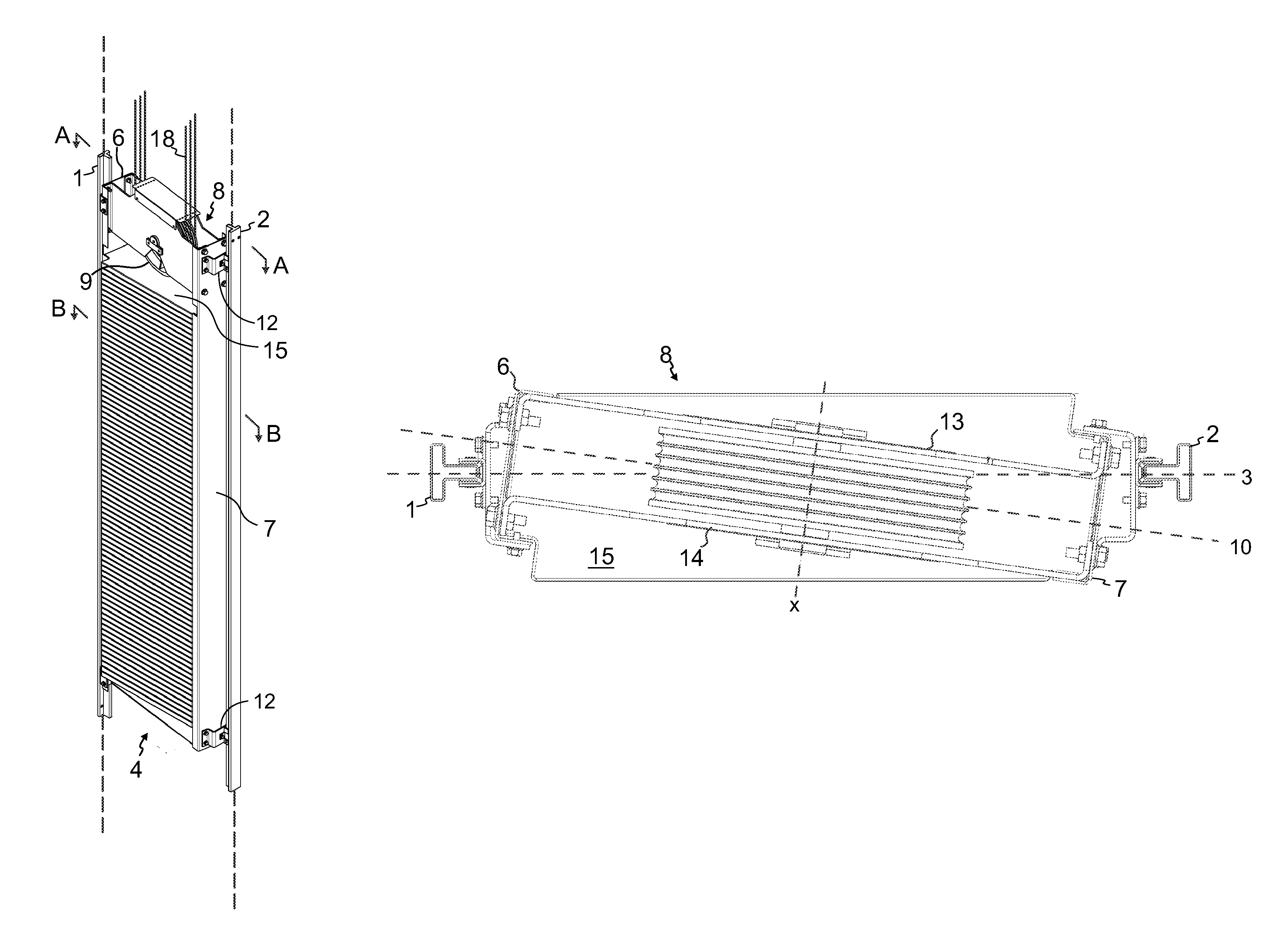
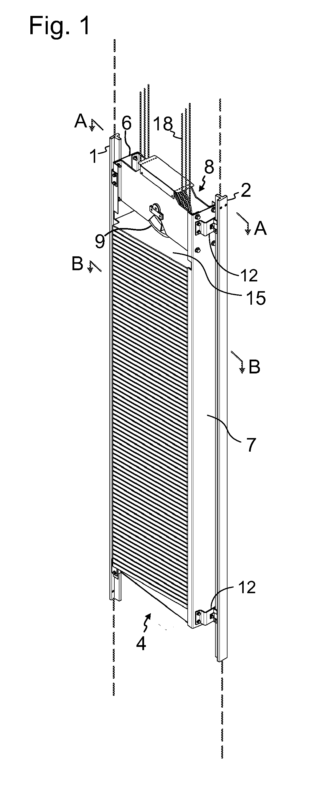
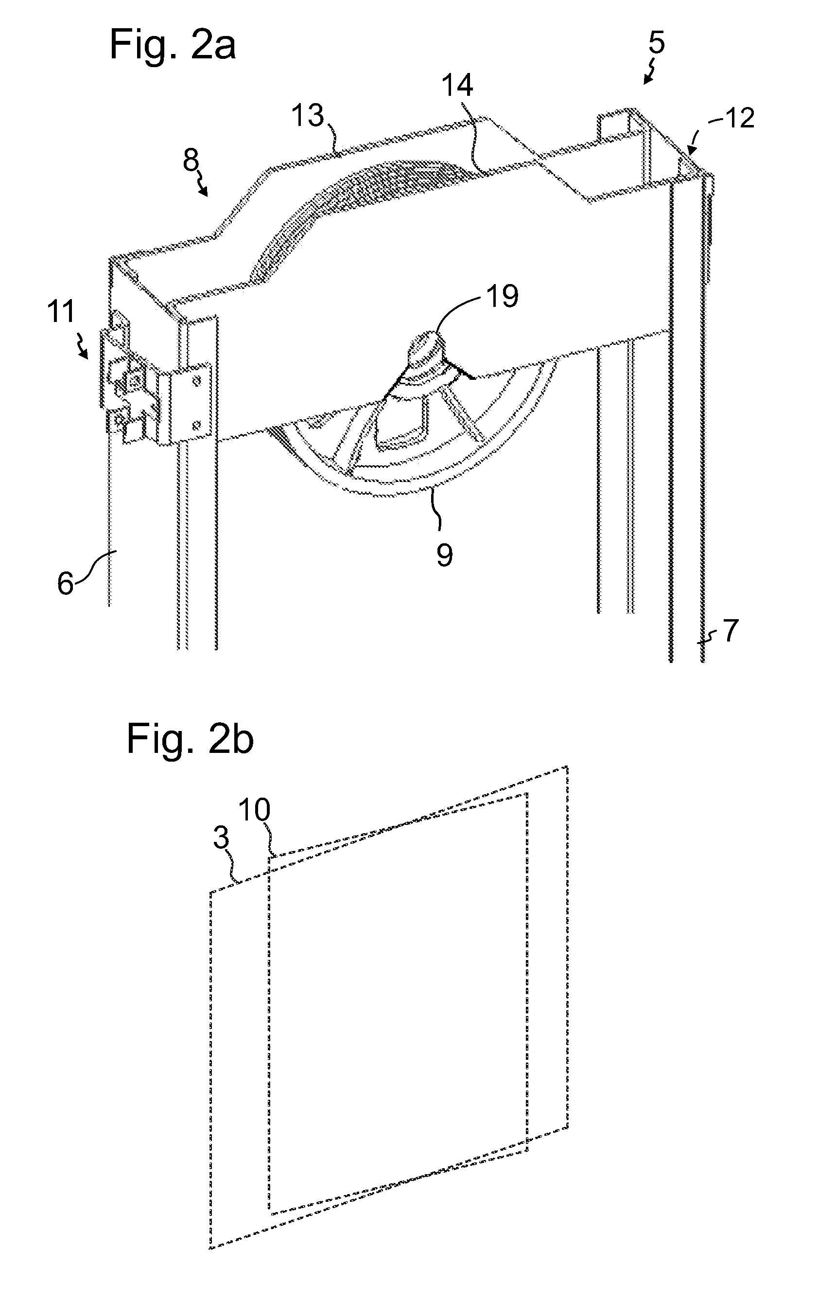
[0026]FIG. 1 illustrates a counterweight arrangement according to a preferred embodiment, which arrangement comprises a first vertical guide rail 1 and a second vertical guide rail 2. Only a short section of the guide rails is illustrated. The guide rails 1 and 2 continue along the dashed line. FIGS. 2, 3a and 3b illustrate the details of the arrangement. Said guide rails 1,2 define a vertical guide rail plane 3, as showed in FIGS. 3a and 3b. In other words, the guide rail plane 3 is the vertical plane on which the vertical guide rails are positioned. The arrangement comprises a counterweight 4 arranged to travel between the guide rails 1, 2 guided by the guide rails 1, 2. The counterweight 4 comprises a frame 5, which comprises a first upright beam 6 and a second upright beam 7 and a cross beam 8 fixed to the upper ends of the uprights 6, 7 thus connecting them. This is implemented by fixing the cross beam to the upper ends of the uprights 6 and 7. A diverting pulley 9 is mounted r...


PUM


Abstract

A counterweight arrangement for an elevator, includes a first vertical guide rail and a second vertical guide rail, the guide rails defining a vertical guide rail plane, a counterweight arranged to travel between the guide rails guided by the guide rails, the counterweight including a frame, which includes a first upright beam and a second upright beam and a cross beam connecting the upper ends of the upright beams, and a diverting pulley mounted between the guide rails on the cross beam of the counterweight frame, the pulley having a vertical plane of rotation, which crosses the guide rail plane. The cross beam is aligned parallel with the plane of rotation of the pulley. An elevator includes the aforementioned counterweight arrangement.

Description

FIELD OF THE INVENTION[0001]The invention relates to an elevator and its counterweight arrangement. The elevator is in particular of the type meant for transporting passengers and / or goods.BACKGROUND OF THE INVENTION[0002]Conventional elevators have a counterweight and an elevator car each traveling vertically guided along two guide rails. The counterweight guide rails extend typically vertically on opposite sides of the counterweight. The plane on which the two guide rails of the counterweight are positioned is called the guide rail plane of the counterweight. The elevator car is typically connected to a counterweight with a suspension roping. This roping may be connected to the counterweight either by fixing an end of the roping to the counterweight or by guiding the roping around one or more pulleys mounted on the counterweight. In the latter case, the pulley is mounted on upper part of the counterweight frame, for instance on the cross beam. In that case, the pulley has been mou...

Claims


Application Information

Patent Timeline
Patent Type & Authority Patents(United States)
IPC IPC(8): B66B17/12B66B11/08
CPCB66B17/12
Inventor ALBU, RAZVANLEHIKOINEN, ERNOFORSSTROM, NIKO
Owner KONE CORP
Why Eureka
Try Eureka