Conductor terminal

Active Publication Date: 2017-01-10
WAGO VERW GMBH
View PDF29 Cites 20 Cited by
  • Summary
  • Abstract
  • Description
  • Claims
  • Application Information

AI Technical Summary

Benefits of technology

The patent describes a compact conductor terminal that has pivot levers mounted in insulating material housing without excessive loading of the housing. The actuation of the levers is also optimized for force effect on the associated spring-loaded clamping connection. The technical effect is a very compact and efficient conductor terminal design.

Problems solved by technology

This leads to a relatively large installation height.

Method used


Image

  • Conductor terminal
  • Conductor terminal
  • Conductor terminal

Examples


first embodiment

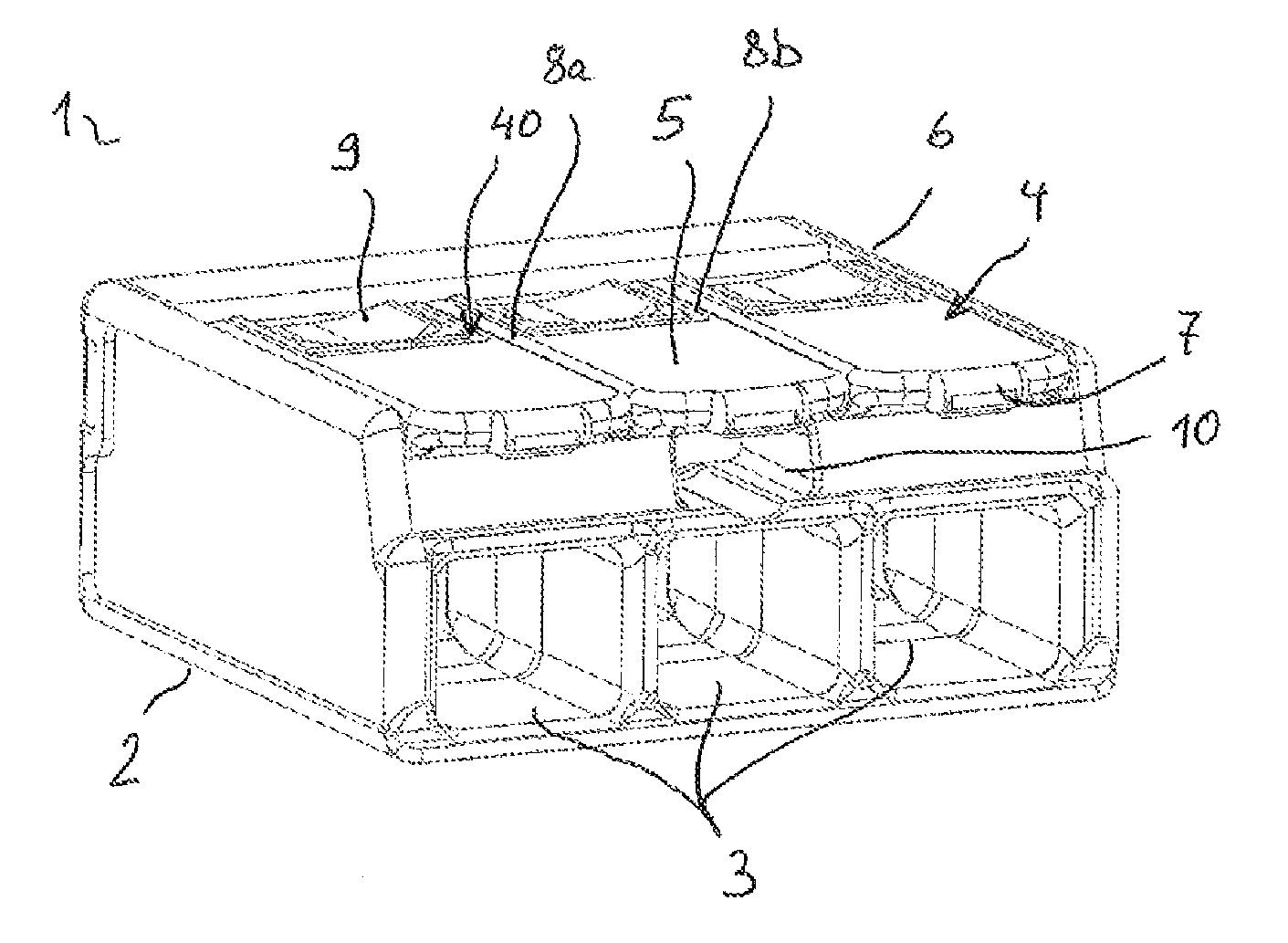
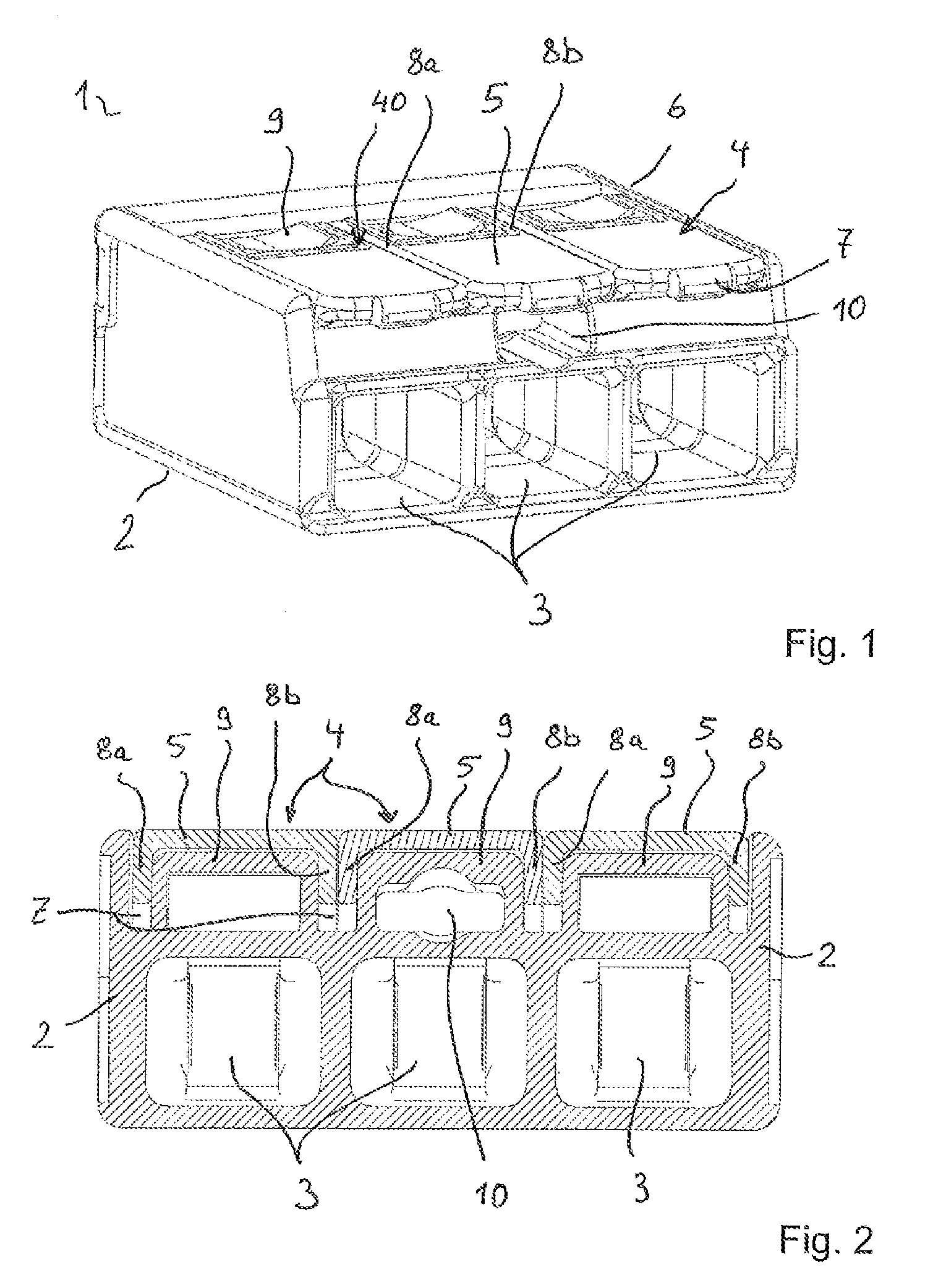
[0046]FIG. 1 shows a perspective view of a conductor terminal 1. The conductor terminal has an insulating material housing 2 with adjacently arranged conductor insertion openings 3 introduced into the insulating material housing from the front. A spring-loaded clamping connection (not visible) arranged in the insulating material housing 2 and associated with a conductor insertion opening 3 is accessible via each of the conductor insertion openings 3. When inserting an electrical conductor into a conductor insertion opening 3, said conductor can be clamped electrically conductively and in a mechanically secured manner at the associated spring-loaded clamping connection.

[0047]An actuation element 4 is arranged above a respective conductor insertion opening. The actuation elements 4 are each mounted in the insulating material housing 2 so as to be pivotable about an axis of rotation. They have a transverse web 5 at the free end, which, as illustrated, lies in the closed position within...

second embodiment

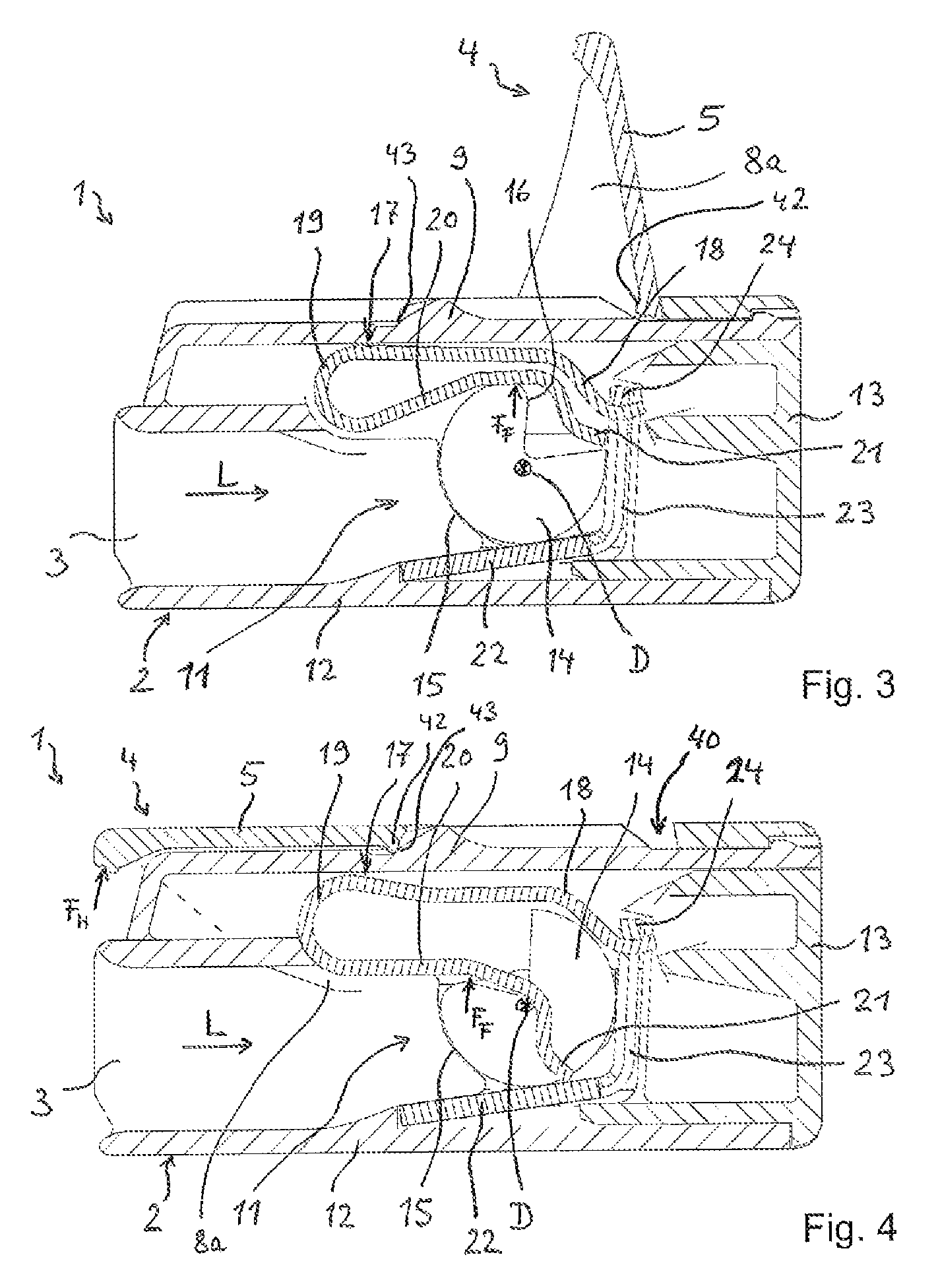
[0079]FIG. 11 shows a side sectional view of a conductor terminal 1 when the actuation element 4 is opened in the open state. Here as well the insulating material housing 2 is formed in two parts from a terminal housing part 12 and a cover part 13 introduced thereinto and latched with the terminal housing part 12. In this embodiment the pivot bearing region 14 has a first at least part-circle bearing region 37, which is adjoined by the actuation portion 16 in the direction of the conductor terminal space offset from the portion 31. It is clear that this portion 31 with the actuation portion 16 has a larger diameter than the part-circle bearing portion 37. The portion 31 with the actuation portion 16 thus protrudes radially relative to the rotary bearing portion 37. The actuation element 4 can then be mounted on the rotary bearing region 37 by suitably matched part-circle bearing cavities of the insulating material housing 2, and where applicable can also be mounted on the larger par...


PUM


Abstract

A conductor terminal (1) having an insulating material housing (2) and having at least one spring-loaded clamping connection (11) in the insulating material housing (2) and also having at least one actuation element (4), which is pivotably accommodated in the insulating material housing (2) and is designed to open in each case at least one associated spring-loaded clamping connection (11), is described. The actuation element (4) has two side wall portions (8a, 8b) which are spaced from one another and at least partially enter the insulating material housing (2) with a pivot bearing region (14) and, opposite said pivot bearing region (14), are connected to each other by a transverse web (5) to form a lever arm. The pivot bearing regions (14) of the mutually distanced side wall portions (8a, 8b) of an actuation element (4) form an axis of rotation (D), about which the actuation element (4) is pivotably mounted in the insulating material housing (2). An associated spring-loaded clamping connection (11) is at least partially accommodated in the space between the pivot bearing regions (14) of an actuation element (4). The pivot bearing regions (14) have actuation portions (16), which in each case are designed in order to act on an associated clamping spring (17) of a spring-loaded clamping connection (11) as the actuation element (16) is pivoted from a closed position into an open position, and in that the actuation portions (4) are arranged on the pivot bearing regions (14) of the side wall portions (8a, 8b) at a distance from one another that is shorter than the distance between the side wall portions (8a, 8b). The actuation portions (16) extend parallel to the side wall portions (8a, 8b) and are formed integrally with the side wall portions (8a, 8b), such that in each case a guide slot (30) is provided between an actuation portion (16) and the associated, directly adjacent side wall portion (8a, 8b), and in that a guide web (27) of the insulating material housing (2) in each case enters an associated guide slot (30) for guiding the actuation element (4) in the event of a pivot motion about an axis of rotation (D) in the pivot bearing region (14).

Description

[0001]This application is a national phase of International Application No. PCT / EP2014 / 052715 filed Feb. 12, 2014.FIELD OF THE INVENTION[0002]The invention relates to a conductor terminal having an insulating material housing and having at least one spring-loaded clamping connection in the insulating material housing and also having at least one actuation element, which is pivotably accommodated in the insulating material housing and is designed to open in each case at least one associated spring-loaded clamping connection.BACKGROUND[0003]Conductor terminals are known in a variety of forms, for example as box terminals, circuit board terminals, series terminals or as conductor terminals in other electrical apparatuses.[0004]DE 299 15 515 U1 discloses a spring clip for connecting electrical conductors to an insulating material housing, which has a terminal with a clamping spring cooperating with a bus bar piece. An actuation element in the form of a cam lever is integrated in the ins...

Claims


Application Information

Patent Timeline
IPC IPC(8): H01R4/48H01R13/639
CPCH01R13/639H01R4/4836H01R4/4845H01R13/6275H01R13/62905H01R4/48455H01R4/48365H01R4/48
Inventor KOLLMANN, HANS-JOSEFGERBERDING, WOLFGANG
Owner WAGO VERW GMBH
Why Eureka
Try Eureka