
Safety gate

a safety gate and gate body technology, applied in the field of safety gates, can solve the problems of rudimentary adjustment system with relatively large adjustment increments, safety gates are difficult to transport and/or store, and the conventional safety gates are rather bulky. , to achieve the effect of extending the length of the top and bottom assemblies

Active Publication Date: 2017-01-10
PILGRIM FAMILY ENTERPRISES
View PDF7 Cites 3 Cited by
  • Summary
  • Abstract
  • Description
  • Claims
  • Application Information

AI Technical Summary

Benefits of technology

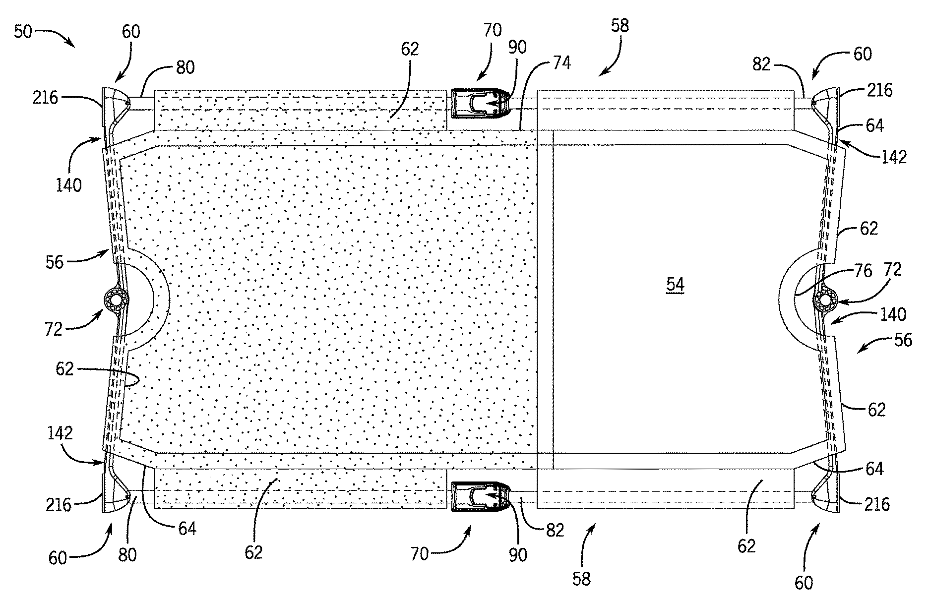
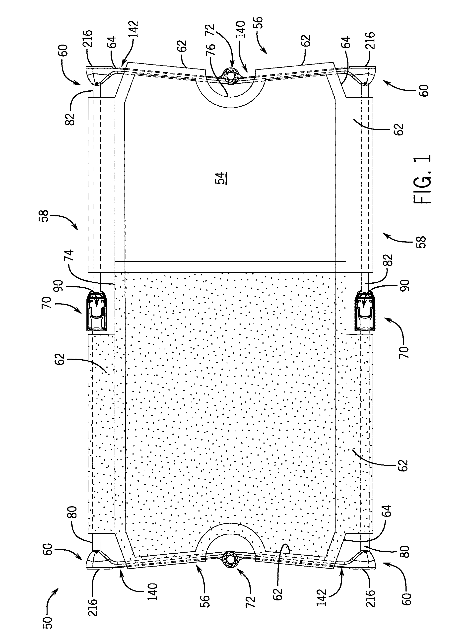
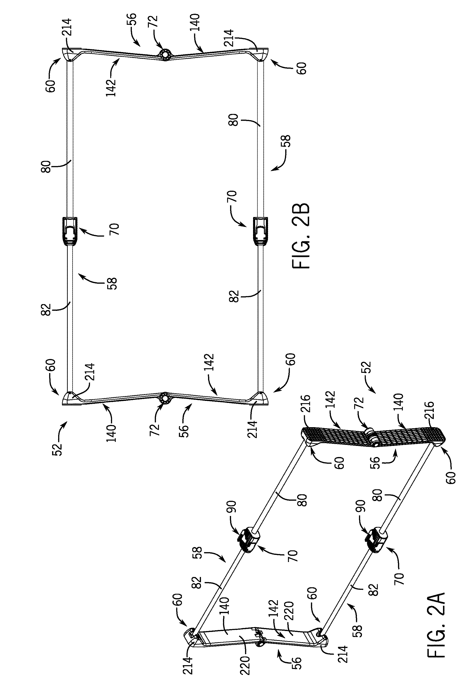
The present invention provides a safety gate that can be adjusted to fit between two surfaces. The gate has top and bottom assemblies and side assemblies that can be extended and retracted to adjust the width of the gate. The flexible barrier is connected to and supported by the frame. The one-way jack mechanisms are carried on each assembly and can be actuated to extend the length of the assemblies and interfereingly fit the gate between the two surfaces. The mechanism prevents the adjustable segment from being retracted back along the fixed segment on the assembly until it is released.

Problems solved by technology

Conventional safety gates tend to be rather bulky and have a rudimentary adjustment system with relatively large adjustment increments.
As a result, safety gates can be difficult to transport and / or store and can be time consuming and frustrating to set-up.
Such safety gates can also be difficult to adjust to precisely fit a given opening.
However, the adjustment sizes can be limited by the relatively large gap between available size increments.
Thus, the gate may be under too much, which may damage the surfaces of the opening, or under too little compression and thus not fully secured in place when installed.
The one-way jack mechanisms, when actuated, incrementally further extend the length of the top and bottom assemblies such that the frame interferingly fits between the two surfaces under compression.
The one-way jack mechanisms, when actuated, incrementally extend the lengths of the top and bottom assemblies such that the frame can interferingly fit between two surfaces under compression in the deployed configuration.

Method used


Image

  • Safety gate
  • Safety gate
  • Safety gate

Examples


Embodiment Construction

[0059]It is the aim of the present invention to provide a safety gate that is safe and secure when installed, is easy to install, is easy to use, and is easy to transport and store. A safety gate is disclosed herein that, when deployed, can be positioned and removably secured in a doorway or other opening between opposed surfaces, such as a doorframe, hallway walls, or stairwell entrance or exit walls. When installed, the disclosed safety gate serves as a barrier to inhibit pets and children from accessing certain rooms, spaces, or floors of a home or dwelling, as desired. The disclosed safety gate employs a frame that is adjustable to allow the gate to be freely expanded and pulled open to a desired length or width to loosely fit within an opening.

[0060]The disclosed safety gate has adjustment or jack mechanisms that can be used to micro-adjust the gate frame in fine or small increments to the length or width necessary to secure the gate in place when installed. The micro-adjustmen...


PUM


Abstract

A safety gate has a frame with top and bottom assemblies spaced apart in a vertical direction and with opposed side assemblies spaced apart in a horizontal direction in a deployed configuration. A length of the top and bottom assemblies is extendable and retractable to adjust a width of the frame between the opposed side assemblies. A flexible barrier is connected to and supported by the frame. A one-way jack mechanism is carried on each of the top and bottom assemblies. The length of the top and bottom assemblies can be extended without actuating the jack mechanisms to adjust the frame to a desired width to loosely fit a space between two surfaces. The one-way jack mechanisms, when actuated, incrementally further extend the length of the top and bottom assemblies such that the frame interferingly fits between the two surfaces under compression.

Description

RELATED APPLICATION DATA[0001]This patent application is a continuation-in-part of U.S. application Ser. No. 13 / 401,880 filed on Feb. 21, 2012 which is related to and claims priority benefit of U.S. provisional patent application Ser. No. 61 / 444,966 filed Feb. 21, 2011 and entitled “Safety Gate.” The entire contents of this prior filed provisional application are hereby incorporated by reference herein.BACKGROUND[0002]1. Field of the Disclosure[0003]The present disclosure is generally directed to safety gates and, more particularly, to a safety gate with a clamp adjustment mechanism for extending the length or width of the safety gate and securely installing the safety gate in an opening.[0004]2. Description of Related Art[0005]Safety gates for preventing children and pets from accessing specific areas in a home or dwelling, such as a stairwell or a particular doorway, are well known in the art. Conventional safety gates, such as the one disclosed in expired U.S. Pat. No. 4,492,263,...

Claims


Application Information

Patent Timeline
Patent Type & Authority Patents(United States)
IPC IPC(8): A47G5/00E06B3/30E06B9/24E06B9/06E06B5/10E06B9/00
CPCE06B9/0692E06B5/10E06B9/00E06B9/06E06B2009/002E05D3/02E05D11/1007
Inventor PILGRIM, GREGALSBERG, KEITHBACKSTROM, MIKAEL
Owner PILGRIM FAMILY ENTERPRISES
Learn More