
Beacon deployment for use with location based services (LBS)

a technology of location based services and beacons, applied in the field of beacons, can solve the problems of inability to utilize prior art devices to display real-time representations of navigating directly from sensors without a central system, inability to meet the needs of users,

Active Publication Date: 2017-01-03
GAMBA GRP HLDG LLC
View PDF88 Cites 107 Cited by
  • Summary
  • Abstract
  • Description
  • Claims
  • Application Information

AI Technical Summary

Benefits of technology

The patent allows users to use Bluetooth devices to locate themselves in an area and communicate with one another in real-time using a local instant messaging system. This eliminates the need for a cellular network and allows for more efficient communication in situations where cellular infrastructure may not be available.

Problems solved by technology

At present, however, no prior art device utilizes the capabilities to display a real-time representation of navigating directly from the sensors without a central system; and without using a Global Positioning System (GPS) based system directly to the user.
This requires an operational, bi-directional communication infrastructure and, additionally, takes time.
This is impractical.
The existing mapping employed by these systems includes the same limitations described previously and is impractical.
Therefore, any indoor services are likely out of the question and the requirement for communication with the Global Positioning System (GPS) limits its availability and accuracy.
Yet, Time of arrival (TOA) is considerably more complex to implement, as it requires a modification to the hardware on the mobile device side, as well as special modifications on the antenna or beacon side.
The use of the Angle of Arrival (AOA) technique is considerably less accurate than using Time of arrival (TOA) technique, due to limited angular resolution and the fact that in an indoor environment, much of the signal can be reflected.
Also, Angle of Arrival (AOA) antennas are more complex, as they require multi-section, highly directional antennas, and multiple RF circuitries.
In this frequency range, radio waves penetrate obstacles, such as walls and human bodies, albeit with a substantial loss.
Bluetooth devices are considered to be a low cost technology, having expected high production volumes (hundreds of millions annually) lead to sub five dollar ($5) cost per chip.
This would eventually result in a low price for the Bluetooth tags or beacons, if and when Bluetooth location systems would become sufficiently ubiquitous.

Method used


Image

  • Beacon deployment for use with location based services (LBS)
  • Beacon deployment for use with location based services (LBS)
  • Beacon deployment for use with location based services (LBS)

Examples


Embodiment Construction

[0664]In all the figures of the drawings, subfeatures and integral parts that correspond to one another bear the same reference symbol.

[0665]Referring now to the drawings in detail and first particularly to FIGS. 1-13 thereof.

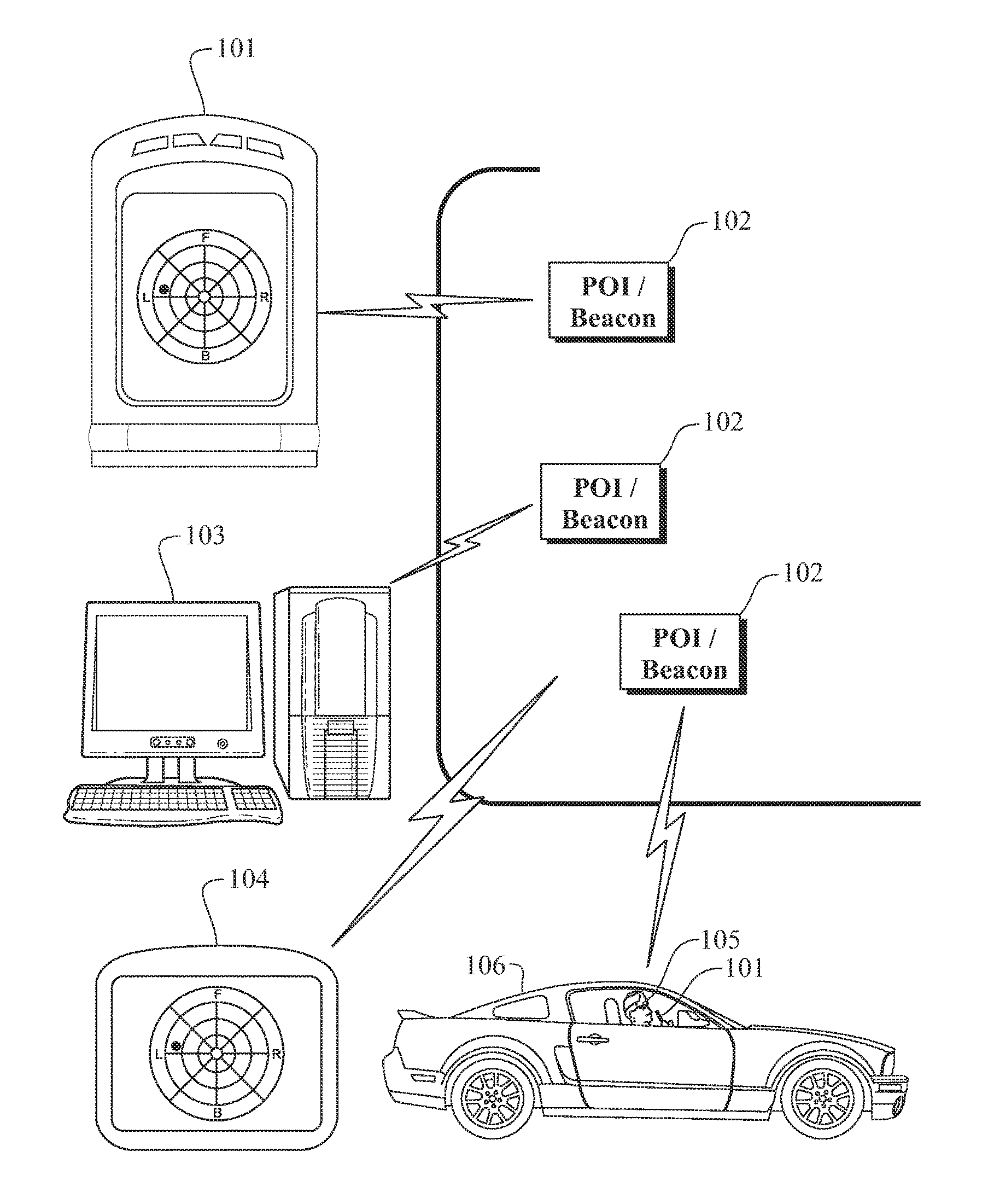
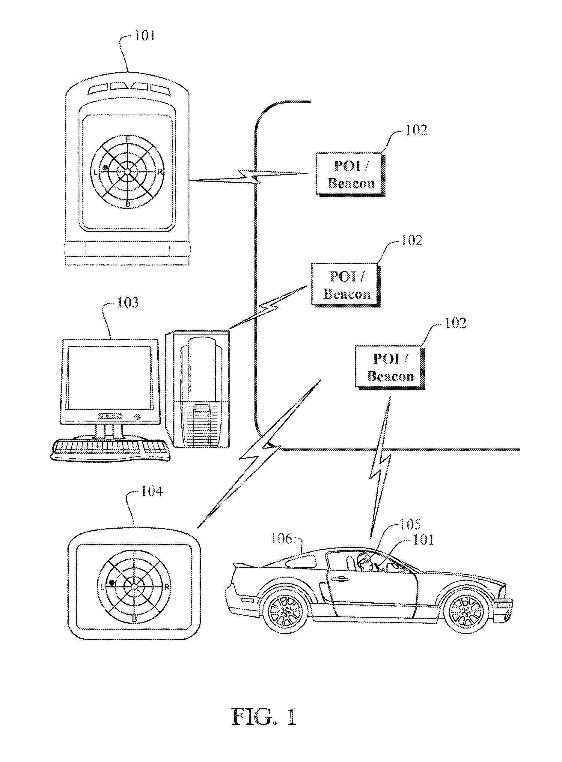
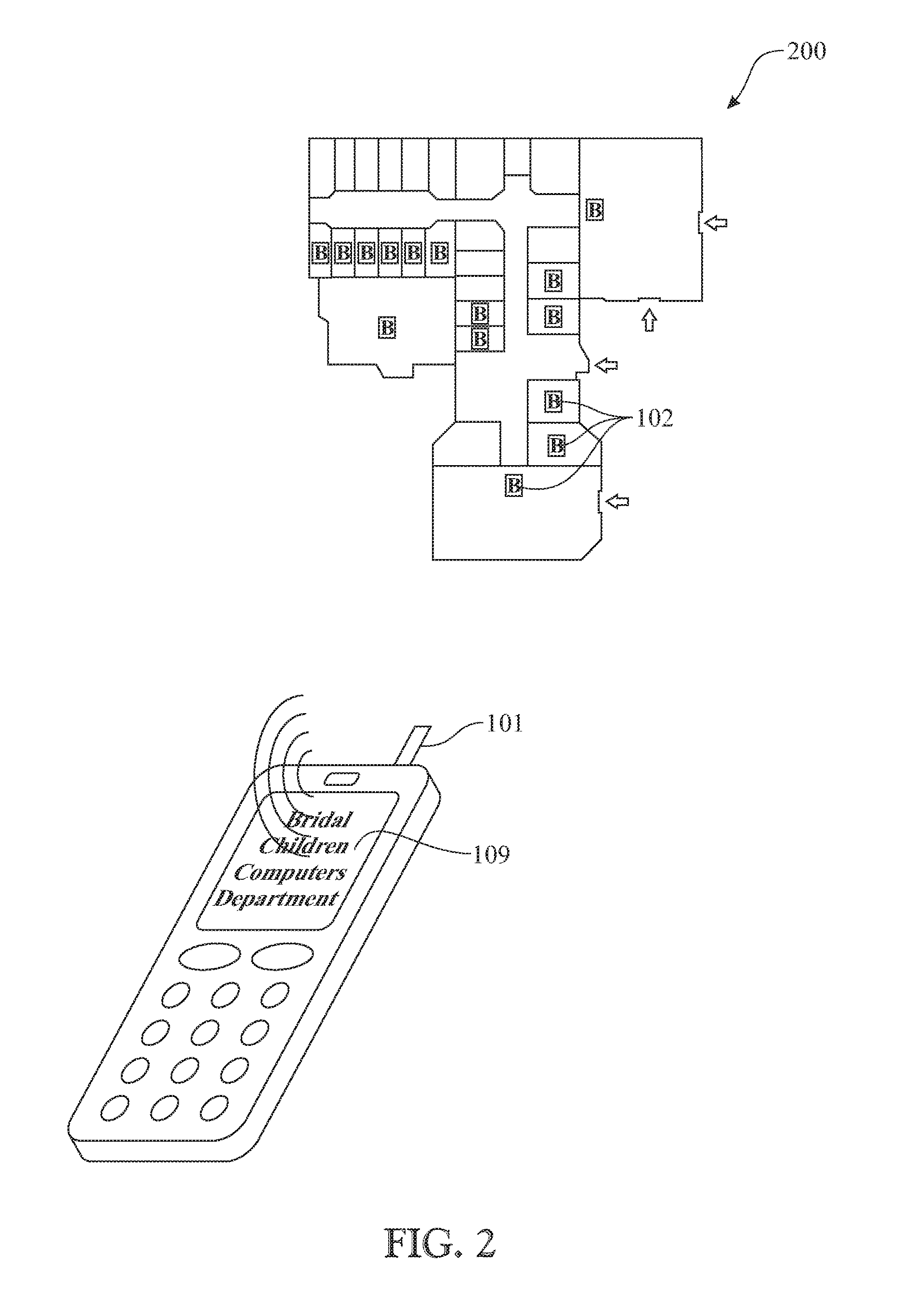
[0666]An exemplary flowchart illustrating a use of Radio Frequency (RF) tags or beacons 102 is presented in FIG. 1. The Radio Frequency (RF) tags or beacons 102 can utilize at least one of Bluetooth and Wi-Fi signal protocols. The exemplary system utilizes a mobile cellular telephone or other suitable mobile device 101 to scan and detect a proximity of an installed Radio Frequency (RF) tag or beacon 102 in the most part for determining a location of the user, assumed to be the same location as the user's cellular telephone 101 in an indoor environment or an outdoor environment. The location in determined by identifying the installed Radio Frequency (RF) tag or beacon 102 in the vicinity of the user's cellular telephone 101, and then using the known location of ...


PUM


Abstract

An infrastructure of Bluetooth and / or Wi-Fi enabled RF tags or beacons deployed within a structure, an urban environment, a residence, buildings, real estate property, in a parking area, etc. The deployed beacons can be integrated with sensors to initiate or trigger an application. The infrastructure being used to recognize a presence of a user within the area to trigger activities, initiate Location Based Services (LBS), provide navigation, provide mapping, convey of information, initiate a link to a server or software, provide support during an emergency, provide assist to E-911 services, trigger an automation function, provide real estate information, and the like.

Description

CROSS REFERENCE TO RELATED APPLICATIONS[0001]This application is:A) is a Divisional Application of U.S. patent application Ser. No. 15 / 086,028 filed on Mar. 30, 2016 (Scheduled to issue as U.S. Pat. No. 9,420,423 on Aug. 16, 2016),[0002]which is a Divisional Application of U.S. patent application Ser. No. 14 / 285,406 filed on May 22, 2014 (currently pending),[0003]which is a Divisional Application of U.S. patent application Ser. No. 14 / 285,332 filed on May 22, 2014 (currently pending),[0004]which is a Divisional Application of U.S. patent application Ser. No. 14 / 285,273 filed on May 22, 2014, (now U.S. Pat. No. 9,204,257 on Dec. 1, 2015),[0005]which is a Divisional Application of U.S. patent application Ser. No. 14 / 285,209 filed on May 22, 2014, (now U.S. Pat. No. 9,204,251 on Dec. 1, 2015),[0006]which is a Divisional Application of U.S. patent application Ser. No. 12 / 930,735 filed on Jan. 14, 2011 (now U.S. Pat. No. 9,020,687 on Apr. 28, 2015),[0007]which is a Divisional Application...

Claims


Application Information

Patent Timeline
Patent Type & Authority Patents(United States)
IPC IPC(8): H04B7/00H04W4/00H04W40/24H04W4/22H04W4/02H04W4/021H04W4/029H04W4/40H04W4/44H04W4/80H04W4/90
CPCH04W4/023H04W4/021H04W4/008H04W40/244H04W4/22H04W4/90H04W4/80H04W76/50G06Q2240/00H04W4/029H04W4/44H04W4/40B60R25/20B60R2325/101B60R2325/103B60R2325/205G01C21/206G01S1/04G01S19/46G06Q20/102H04W48/10G01S5/0231
Inventor MENDELSON, EHUD
Owner GAMBA GRP HLDG LLC
Learn More