
Devices for mobilizing the hip joint capsule and methods of using same

a hip joint capsule and hip joint technology, applied in the field of hip joint capsule devices and hip joint capsule mobilization methods, can solve the problems of increased pain, loss of hip joint range of motion and strength, and uncomfortable conventional treatment methods for patients, so as to delay total hip replacement, restore normal hip range of motion, and restore pain-free hip motion

Inactive Publication Date: 2016-12-20
STEELE CARL W
View PDF16 Cites 1 Cited by
  • Summary
  • Abstract
  • Description
  • Claims
  • Application Information

AI Technical Summary

Benefits of technology

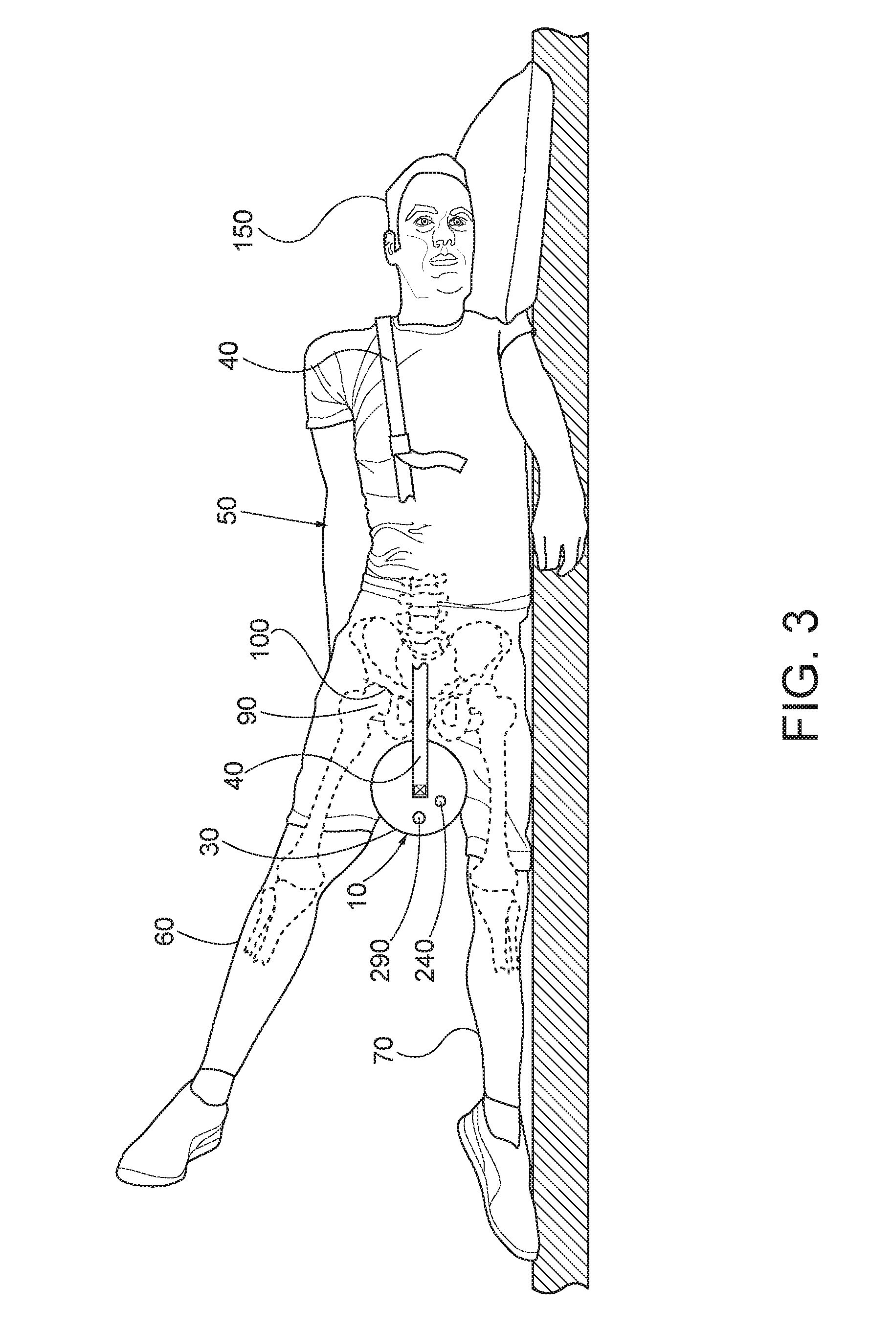
[0010]In one method of the invention, the patient assumes a lateral position, with the hip capsule to be mobilized superior. A bolster is placed between the patient's legs proximal to patient's crotch (i.e., the bolster is positioned as near the user's crotch as possible, with the longitudinal axis of the device placed approximately transverse to the patient's superior femur). The bolster thus positioned is capable of serving as a partially compressible fulcrum, with the superior femur serving as a lever arm, to create a first class lever that partially distracts the femoral head of the superior hip from the acetabulum. The degree of hip flexion and rotation is preferably varied to affect different regions of the hip capsule. Devices and methods of the invention provide for mobilization, stretching and / or expansion of the hip joint capsule, restoration of normal hip range of motion, restoration of pain free hip motion and a consequent reduction and / or delay of total hip replacements.

Problems solved by technology

Injuries and other conditions can result in a loss of range of motion and strength at the hip joint.
The conventional treatment methods are often uncomfortable for the patient.
And forced range of motion often results in increased pain and therefore limited compliance.
And, the belt technique is extremely labor intensive insofar as the therapist is concerned.
It is generally poorly tolerated when adequate force to distract the hip joint is applied.
And, force is limited because the patient will slide off the treatment table unless the pelvis is also restrained by a stabilizing strap.

Method used


Image

  • Devices for mobilizing the hip joint capsule and methods of using same
  • Devices for mobilizing the hip joint capsule and methods of using same
  • Devices for mobilizing the hip joint capsule and methods of using same

Examples


Embodiment Construction

[0024]FIG. 1 is a perspective view of an exemplary bolster 10 according to the invention, and FIG. 2 is a section view taken perpendicular to the longitudinal axis 20 of the bolster 10 shown in FIG. 1 along the line 2-2. The bolster 10 is a resilient member, which in accordance with the method of the invention, is disposed between the patient's legs proximal to the patient's crotch such that it supports the weight of the patient's superior leg, in a resting position, in a spaced-apart relationship relative to the patient's inferior leg. The bolster 10 must be a resilient structure such that when a force is applied to the patient's superior leg sufficient to move it downwardly below the resting position with the bolster thus disposed, the bolster partially deforms but also functions as a fulcrum with the patient's superior femur functioning as a first class lever to partially distract the patient's superior femoral head from the patient's superior acetabulum. After the application of...


PUM


Abstract

A method for mobilizing a hip joint capsule of a patient using a resilient bolster. In accordance with the method, the patient assumes a lateral position, with the hip capsule to be treated superior. The resilient bolster is placed between the patient's legs as proximal to the patient's crotch. A force is applied to patient's superior leg to move it downwardly from a resting position. During downward movement of the patient's superior leg, the bolster functions as a fulcrum and the patient's superior femur functions as a lever arm to create a first class lever that partially distracts the femoral head from the acetabulum. After application of the force, the resiliency of the bolster causes the patient's superior leg to return to the resting position. The movements may be repeated, and the degree of hip flexion and rotation may be varied to affect different regions of the hip capsule.

Description

BACKGROUND OF INVENTION[0001]Field of Invention[0002]The present invention relates to devices for use in mobilizing a hip joint capsule and methods for mobilizing a hip joint capsule that utilize the same.[0003]Description of Related Art[0004]The acetabulofemoral joint (i.e., the hip joint) is the joint between the femur and the acetabulum of the pelvis. Its primary function is to support the weight of the body in both static (e.g., standing) and dynamic (e.g., walking or running) postures.[0005]The articular capsule of the hip joint is strong and dense. It attaches to the hip bone outside the acetabular lip, which thus projects into the capsular space. On the femoral side, the distance between the head's cartilaginous rim and the capsular attachment at the base of the neck is constant, which leaves a wider extracapsular part of the neck at the back than at the front. The strong but loose fibrous capsule of the hip joint permits the hip joint to have the second largest range of move...

Claims


Application Information

Patent Timeline
Patent Type & Authority Patents(United States)
IPC IPC(8): A61H1/02
CPCA61H1/0244A61H2001/0248A61H2201/0103A61H2201/0134A61H2201/0157A61H2201/1284A61H2201/1614A61H2201/1628A61H2201/1652A61H2201/5071A61H9/005
Inventor STEELE, CARL W.
Owner STEELE CARL W
Learn More