
Magnet assisted orthotic brace

a technology of orthotic braces and magnets, applied in the field of orthotic braces, can solve problems such as disorientation of joint surfaces, and achieve the effects of reducing joint bone force, influencing joint surfaces, and reducing joint flexion

Inactive Publication Date: 2016-12-20
THE LONNIE & SHANNON PAULOS TRUST AS AMENDED & RESTATED
View PDF3 Cites 5 Cited by
  • Summary
  • Abstract
  • Description
  • Claims
  • Application Information

AI Technical Summary

Benefits of technology

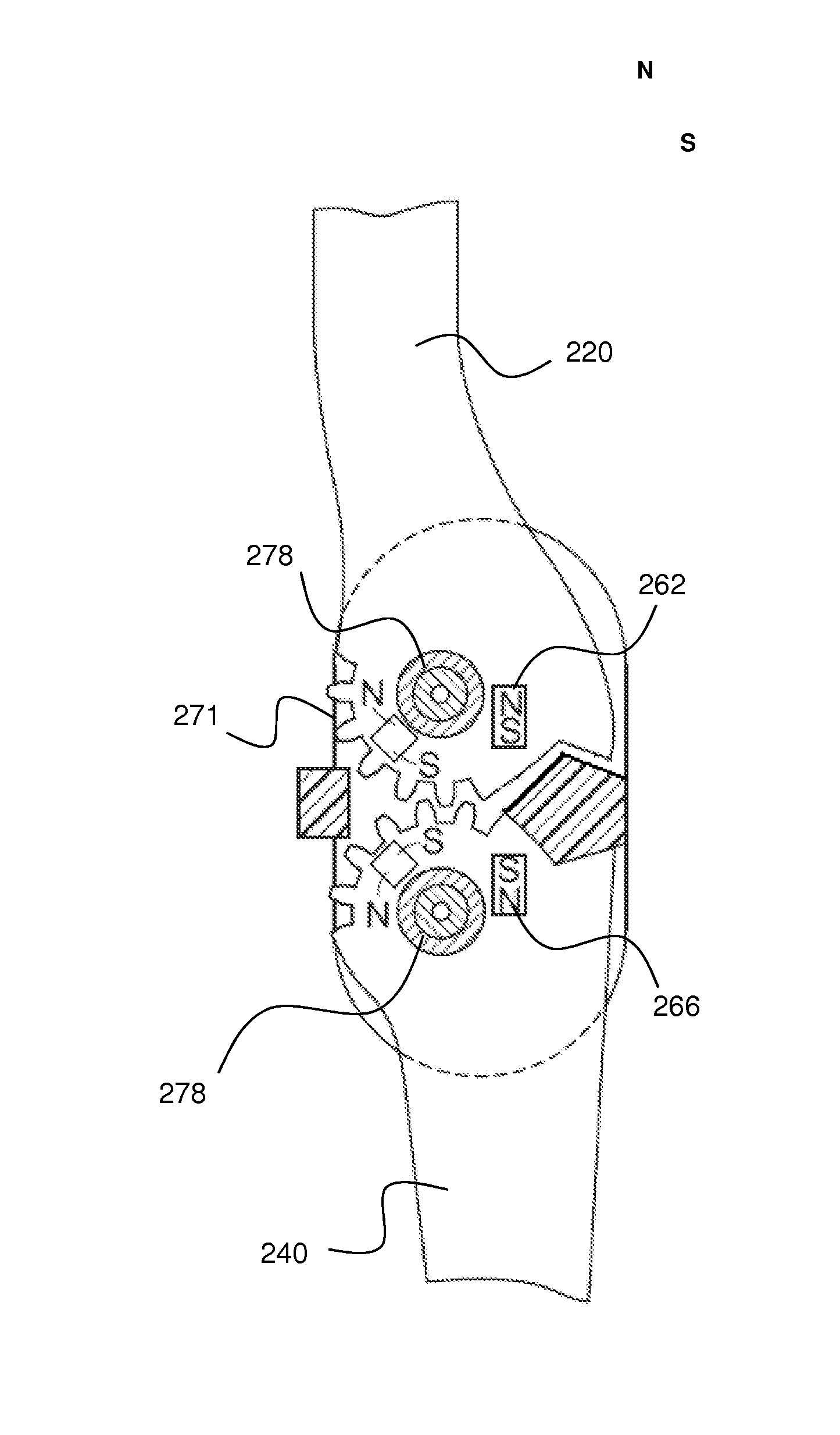
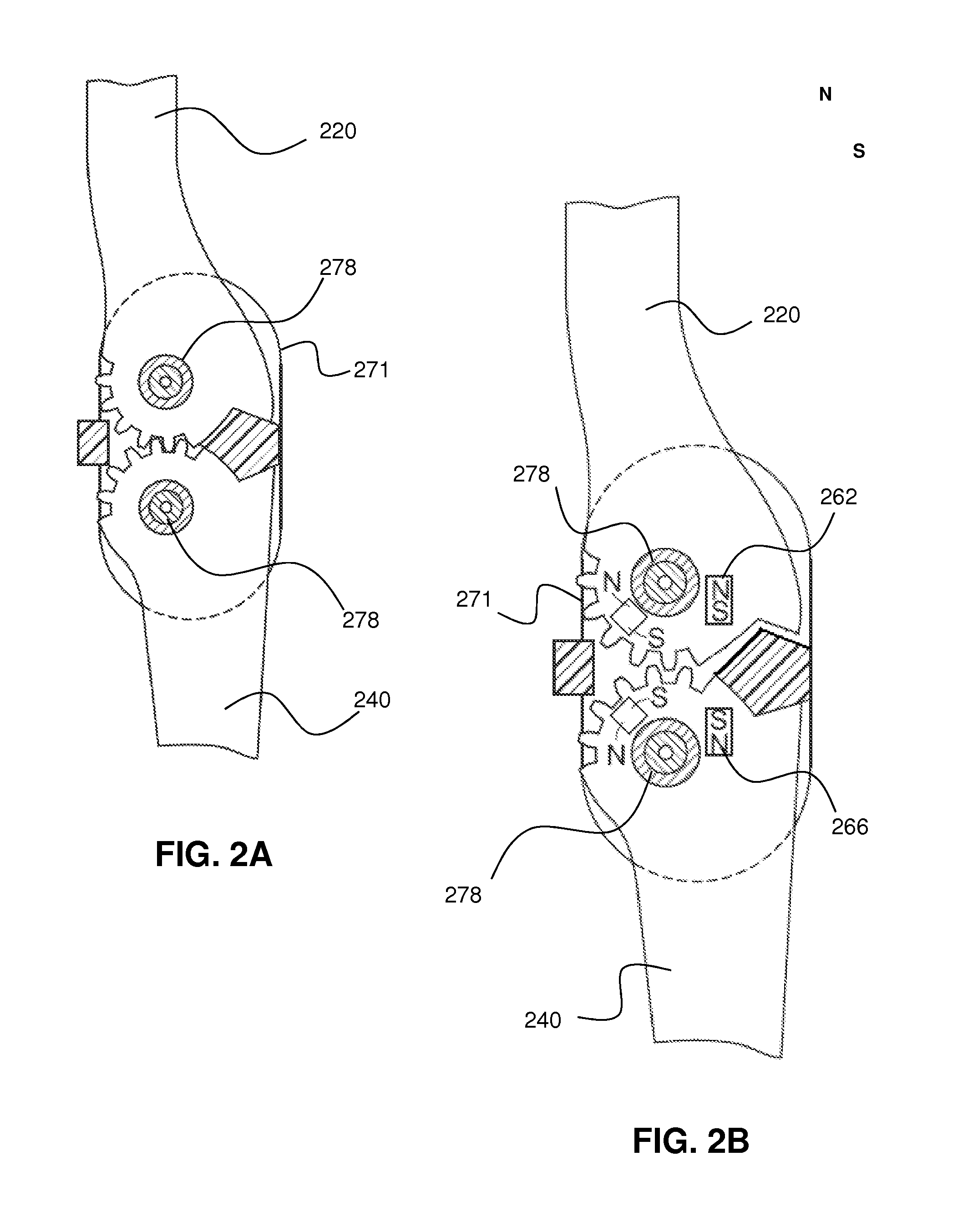
[0012]It is an object of one embodiment of the disclosed orthotic brace to combine load shifting capabilities of specialty bracing with the added force of magnetic repulsion through a portion or complete range of knee motion. Some embodiments of the specially designed brace and hinge can re-direct repulsion forces into one or more superior / inferior directions, thus distracting the joint surfaces on the side of the joint that the hinge / magnet system is applied. Some embodiments of the brace also provide the ability to influence the joint through greater degrees of flexion.
[0013]Some embodiments of the brace and hinge design are capable of reducing the force put on joint bones as well was influence the bones in pre-determined manner to bias the joint into certain positions or to vary the force in different points of joint flexion.

Problems solved by technology

Some embodiments of the specially designed brace and hinge can re-direct repulsion forces into one or more superior / inferior directions, thus distracting the joint surfaces on the side of the joint that the hinge / magnet system is applied.

Method used


Image

  • Magnet assisted orthotic brace
  • Magnet assisted orthotic brace
  • Magnet assisted orthotic brace

Examples


Embodiment Construction

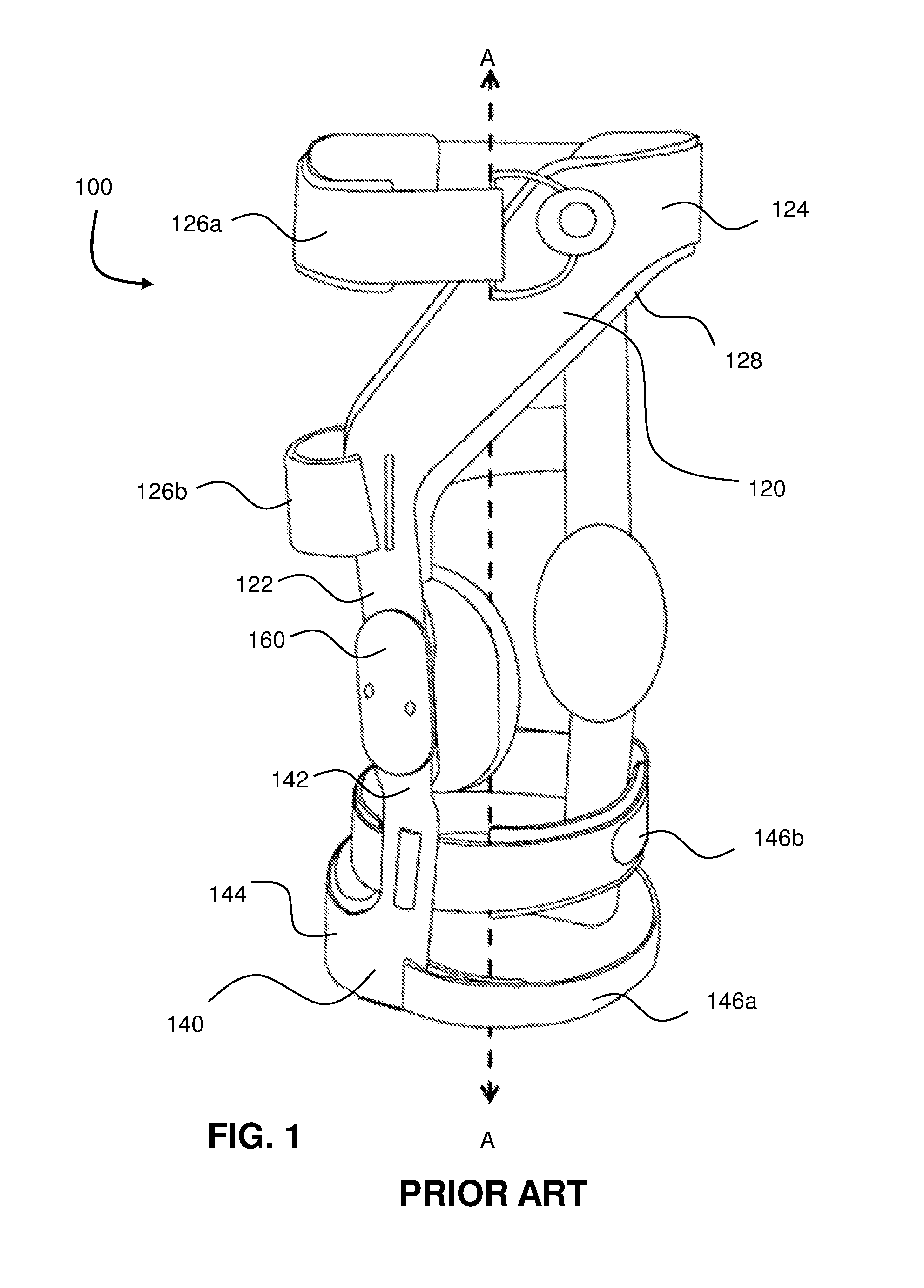
[0034]A magnet assisted orthotic brace system will now be described in detail with reference to the accompanying drawings. It will be appreciated that, while the following description focuses on an orthotic brace system that uses magnetic forces to reduce joint forces on a knee, the systems and methods disclosed herein have wide applicability. For example, the orthotic brace system described herein may be readily employed with other joints on a patient's body such as knee, finger, elbow, wrist or shoulder joints. Notwithstanding the specific example embodiments set forth below, all such variations and modifications that would be envisioned by one of ordinary skill in the art are intended to fall within the scope of this disclosure.

[0035]Some embodiments of the disclosed brace and hinge can require fewer straps and less prominent hinges by virtue of the size and placement of one or more magnets in a magnetic array. The magnets are placed so as to repel or attract each other as they c...


PUM


Abstract

An orthotic brace and brace hinge where the brace comprises two hinge elements operably connected and at least one hinge element having a magnetic field that provides a magnetic force urging one of the hinge elements in a pre-determined direction. Embodiments of the present invention generally utilize magnetic forces to stabilize, influence and / or maintain adjacent joint portions in pre-determined desired relationships and for constraining motion and / or rotation of the joint portions. Through the use of the repelling and attracting forces of magnets, mechanical forces in the brace and brace hinge can be replaced or supplemented to reduce the force put on joint bones, to influence the bones so that the joint is biased into certain positions or to apply different forces through different points of joint flexion. Embodiments of braces with magnetic fields on other brace elements are also disclosed.

Description

CROSS-REFERENCE TO RELATED APPLICATIONS[0001]This application is a Continuation of U.S. patent application Ser. No. 12 / 781,212 filed on 17 May, 2010, entitled “MAGNET ASSISTED ORTHOTIC BRACE” file to Lonnie Paulos; U.S. patent application Ser. No. 12 / 781,212 claims benefit to U.S. Patent Application No. 61 / 179,359 filed on 18 May, 2009, entitled “MAGNET ASSISTED ORTHOTIC BRACE” to Lonnie Paulos; the entire content of each application referenced above is incorporated by reference in their entirety.STATEMENT REGARDING FEDERALLY SPONSORED RESEARCH OR DEVELOPMENT[0002]Not ApplicableREFERENCE TO SEQUENCE LISTING, A TABLE, OR A COMPUTER PROGRAM LISTING COMPACT DISC APPENDIX[0003]Not Applicable.BACKGROUND OF THE INVENTION[0004]Field of the Invention[0005]Embodiments of the present invention relate to assisting orthotic braces in reducing or influencing the load on and between bone portions of a joint or shifting the weight bearing load on one compartment of the joint to another. Embodiment...

Claims


Application Information

Patent Timeline
Patent Type & Authority Patents(United States)
IPC IPC(8): A61F5/00A61F5/01
CPCA61F5/0102A61F5/01A61F5/0106A61F5/0585A61F2005/0137A61F2005/0139A61F2005/0148A61F2005/0179A61F5/0125
Inventor PAULOS, LONNIE E.
Owner THE LONNIE & SHANNON PAULOS TRUST AS AMENDED & RESTATED
Learn More