Receiver, transmission system, method for receiving polarization multiplexed optical signal, and non-transitory computer readable medium storing receiver control program
a transmission system and receiver technology, applied in the direction of electromagnetic transmission, phase-modulated carrier system, electrical apparatus, etc., can solve problems such as difficulty in appropriately receiving signals, and achieve the effect of stabilizing reception characteristics
- Summary
- Abstract
- Description
- Claims
- Application Information
AI Technical Summary
Benefits of technology
Problems solved by technology
Method used
Image

Examples
first exemplary embodiment
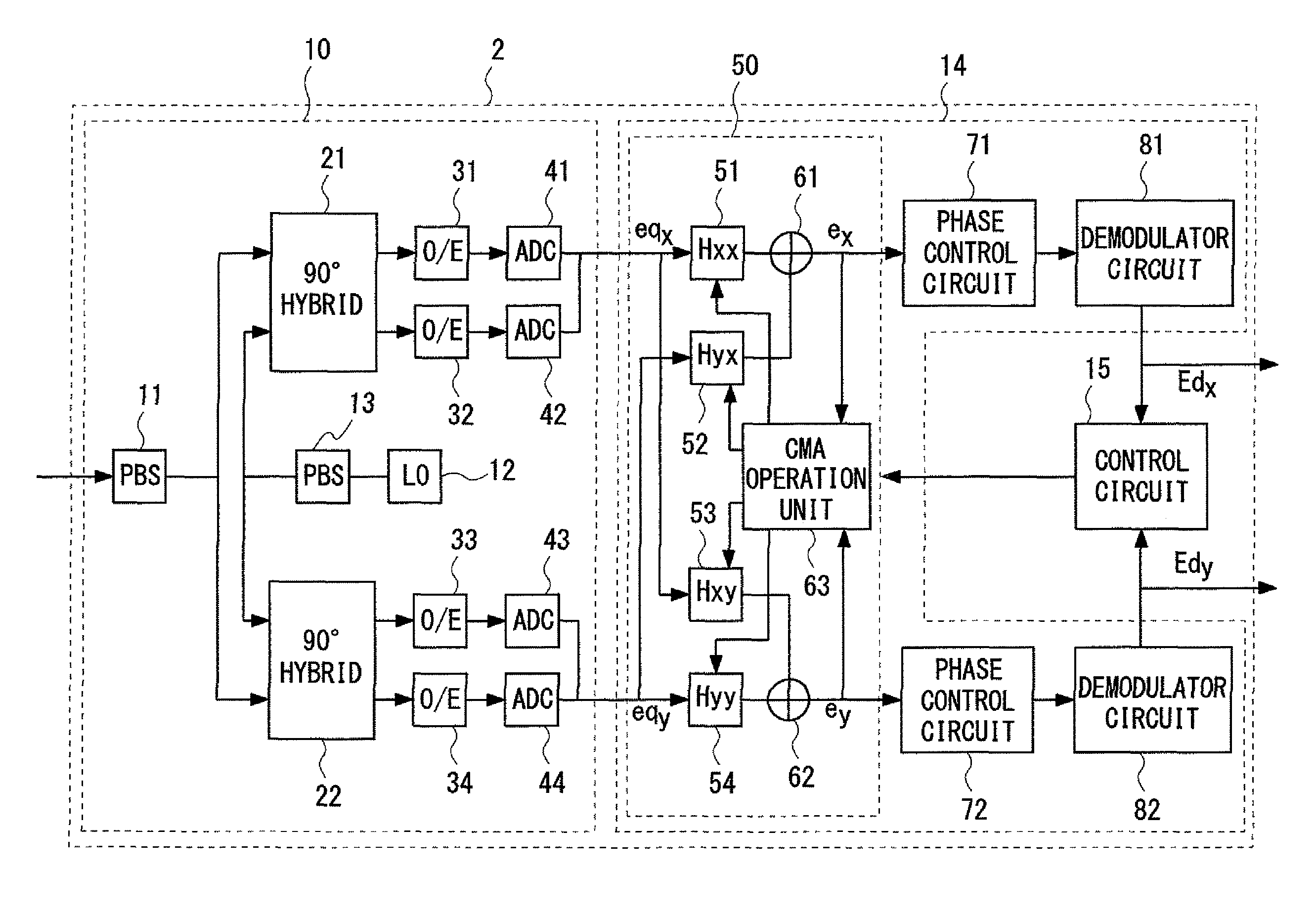
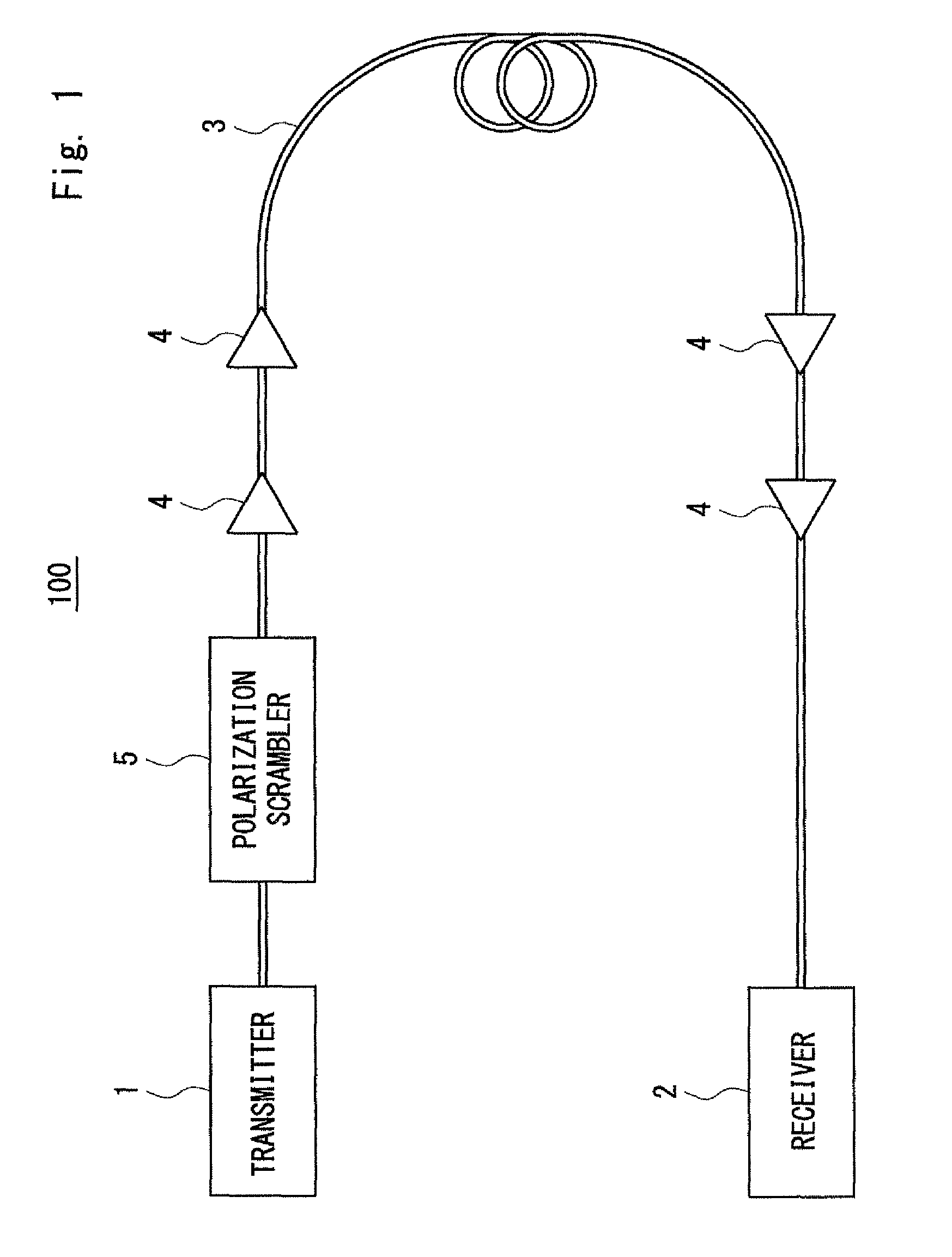
[0030]First, a transmission system 100 according to a first exemplary embodiment of the present invention will be described. FIG. 1 is a block diagram showing the configuration of the transmission system 100 according to the first exemplary embodiment. The transmission system 100 includes a transmitter 1, a receiver 2, a transmission line 3, optical amplifiers 4, and a polarization scrambler 5.
[0031]The transmitter 1 outputs, as an optical signal, a DP-QPSK optical signal which has been subjected to dual polarization-quadrature phase shift keying (hereinafter referred to as “DP-QPSK”). In other words, the DP-QPSK optical signal output from the transmitter 1 includes X-polarization and Y-polarization which have polarization planes orthogonal to each other. The X-polarization and the Y-polarization are quadrature phase shift keying (hereinafter referred to as “QPSK”) optical signals.
[0032]The transmitter 1 and the receiver 2 are optically connected to each other by the transmission li...
second exemplary embodiment
[0080]Next, a transmission system 200 according to a second exemplary embodiment of the present invention will be described. The transmission system 200 has a configuration similar to that of the transmission system 100, and thus the description of the configuration is omitted. The transmission system 200 differs from the transmission system 100 in the calibration operation performed by the control circuit 15 for the receiver 2. The calibration operation performed by the control circuit 15 will be described below. FIG. 6 is a flowchart showing the calibration operation in the transmission system 200 according to the second exemplary embodiment. Steps S21 to S25 shown in FIG. 6 are respectively similar to steps S11 to S15 shown in FIG. 4, and thus the description thereof is omitted.
[0081]Even when the amplitude or phase variation D of each of the X-polarization and the Y-polarization is equal to or less than the standard value DSTD the reception of the X-polarization and the receptio...
third exemplary embodiment
[0090]Next, a transmission system 300 according to a third exemplary embodiment of the present invention will be described. The transmission system 300 has a configuration similar to that of the transmission system 100, and thus the description of the configuration is omitted. The transmission system 300 is an application example of the transmission system 100, and differs from the transmission system 100 in that an operation (standard calculation operation) for determining a standard range in a calibration operation is performed prior to the calibration operation performed by the control circuit 15 for the receiver 2.
[0091]As described above in the first and second exemplary embodiments, the control circuit 15 compares the standard range with the amplitude or phase variation of each of the X-polarization and the Y-polarization (step S12 in FIG. 4 and step S22 in FIG. 6). Accordingly, it is necessary to determine the standard range in advance. This exemplary embodiment illustrates a...
PUM
 Abstract
Description
Claims
Application Information
 - R&D
- Intellectual Property
- Life Sciences
- Materials
- Tech Scout
- Unparalleled Data Quality
- Higher Quality Content
- 60% Fewer Hallucinations
Browse by: Latest US Patents, China's latest patents, Technical Efficacy Thesaurus, Application Domain, Technology Topic, Popular Technical Reports.
© 2025 PatSnap. All rights reserved.Legal|Privacy policy|Modern Slavery Act Transparency Statement|Sitemap|About US| Contact US: help@patsnap.com