
Space suit helmet display system

a display system and helmet technology, applied in the field of helmet display systems, can solve the problems of insufficient head and helmet mounted display system designs for the next generation of spacesuits, inability to direct adopt the above display system designs, and strong disfavor of astronauts who wear anything mounted to their head within their helmets

Active Publication Date: 2016-11-22
HONEYWELL INT INC
View PDF42 Cites 7 Cited by
  • Summary
  • Abstract
  • Description
  • Claims
  • Application Information

AI Technical Summary

Problems solved by technology

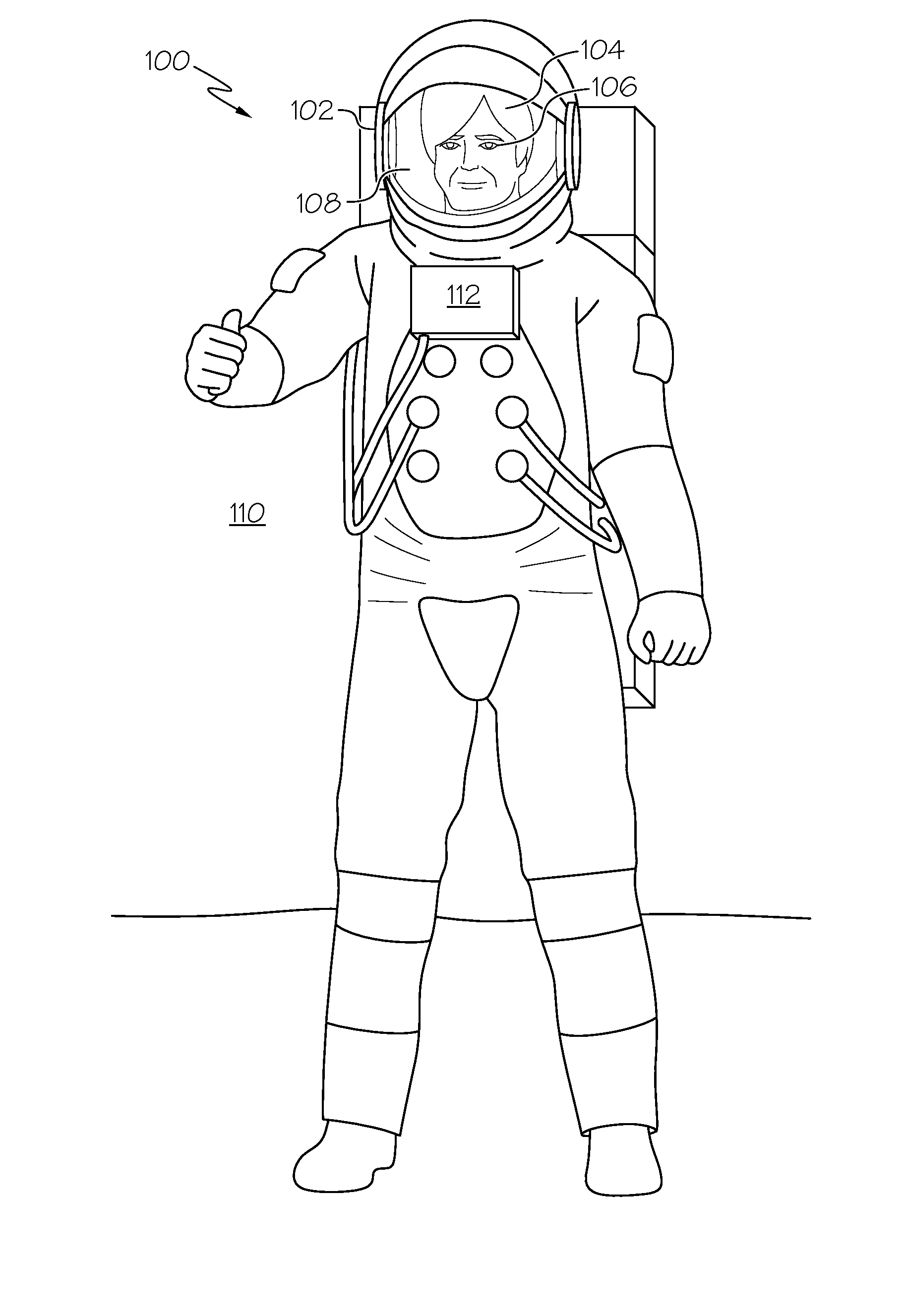
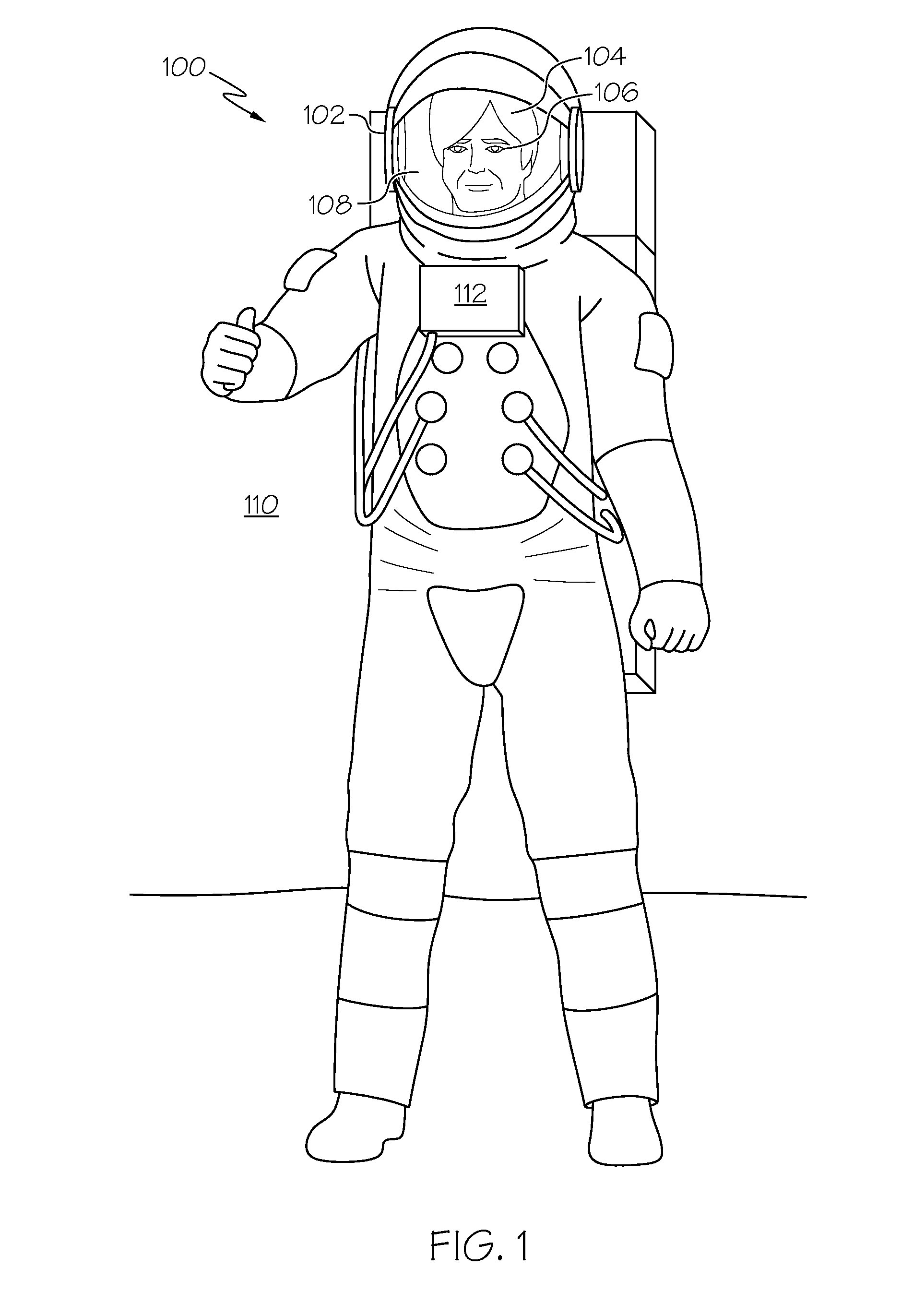
While current display technology may satisfy the image-generating requirements of new space suit helmet displays, current head and helmet mounted display system designs are insufficient for the next generation spacesuit.
While the above described head and helmet mounted display systems offer distinct advantages, issues that are unique to space suit helmets make direct adoption of the above display system designs impractical.
First, having the astronaut wear anything mounted to his head within his helmet is strongly disfavored due to the inability to adjust or reposition it, the additional time required to don or doff the suit over head mounted equipment, and being a potential impact hazard as the astronaut's head moves within the helmet.
It can also be readily appreciated that placing electronics inside the oxygen-rich, pressurized, bubble of the space suit helmet increases fire risk and the associated cost of performing quality assurance testing.
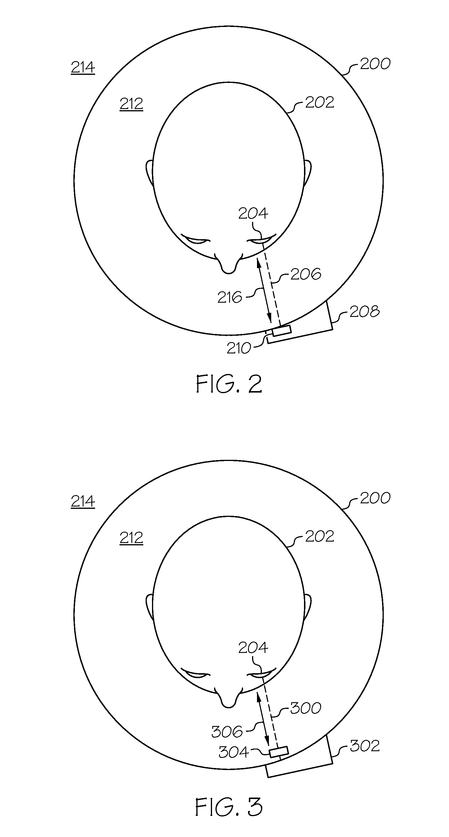
Next, unlike motorcycle helmets, a space suit helmet is non-conformal; therefore mounting a display system to the helmet introduces misalignment issues as the astronaut's head moves around within the helmet.

Method used


Image

  • Space suit helmet display system
  • Space suit helmet display system
  • Space suit helmet display system

Examples


Embodiment Construction

[0019]The following Detailed Description is merely exemplary in nature and is not intended to limit the embodiments of the subject matter or the application and uses of such embodiments. As used herein, the word “exemplary” means “serving as an example, instance, or illustration.” Any implementation described herein as exemplary is not necessarily to be construed as preferred or advantageous over any other implementations. Furthermore, there is no intention to be bound by any expressed or implied theory presented in the preceding Technical Field, Background, Brief Summary or the following Detailed Description.

[0020]For the sake of brevity, conventional techniques related to graphics and image processing, sensors, and other functional aspects of certain systems and subsystems (and the individual operating components thereof) may not be described in detail herein. Furthermore, the connecting lines shown in the various figures contained herein are intended to represent exemplary functi...


PUM


Abstract

A space suit helmet capable of meeting the demands of future space suit helmet display requirements in a decoupled-helmet, helmet-mounted design with sufficient eye relief is provided. A display system and a redirecting assembly are coupled together and mounted to the helmet. The display system generates an image and the redirecting assembly orients the image with respect to a predetermined valid eye location volume within the helmet.

Description

TECHNICAL FIELD[0001]Embodiments of the subject matter described herein relate generally to helmet display systems and, more particularly, to helmet display systems suitable for use in space suits.BACKGROUND[0002]Enhanced helmet display requirements, for example, those promulgated by the National Aeronautics and Space Administration (NASA), have been imposed on the next generation of space suits suitable for extra-vehicular activity (EVA). Some non-limiting examples of the new requirements include full color graphical displays including continually updated procedures, checklists, photo imagery, and video. Current space suits that are suitable for extra-vehicular activity (EVA) generally utilize small one line, 12 character alpha-numeric display panels located on the external surface of the space suit, often in the chest or trunk area, and display a limited set of suit system data. While current display technology may satisfy the image-generating requirements of new space suit helmet...

Claims


Application Information

Patent Timeline
Patent Type & Authority Patents(United States)
IPC IPC(8): G02B27/01G06F3/01
CPCG02B27/0172G06F3/013G02B2027/0123G02B2027/0127G02B2027/0187
Inventor DOPILKA, DAVID J.SCHUCK, DARYL
Owner HONEYWELL INT INC
Learn More