
Molded case circuit breaker accessory wiring improvement

a circuit breaker and accessory wire technology, applied in the direction of protective switch details, protective switch terminals/connections, coupling device connections, etc., can solve the problems of limited number of wires that can pass through the slots provided on the sides of the molded case circuit breakers, and unsafe conditions

Active Publication Date: 2016-11-08
EATON INTELLIGENT POWER LTD
View PDF14 Cites 21 Cited by
  • Summary
  • Abstract
  • Description
  • Claims
  • Application Information

AI Technical Summary

Problems solved by technology

As a result, the wires are generally thick and therefore the number of wires that can pass through each of the slots provided on the sides of the molded case circuit breakers is limited.
Further, additional engineering of the connection wires to the accessory components may be provided in order to satisfy pull test requirements to assure that the wires cannot be pulled out of the breaker (e.g., by an operator or a customer) causing an unsafe condition.

Method used


Image

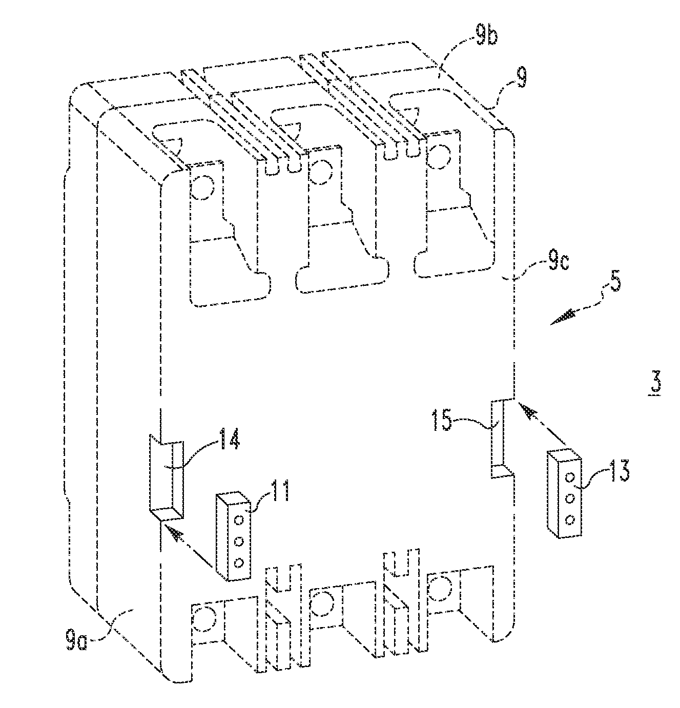
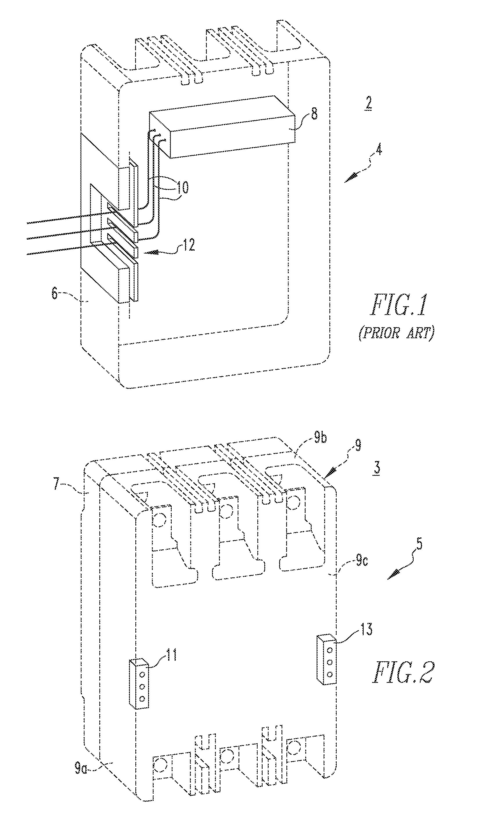
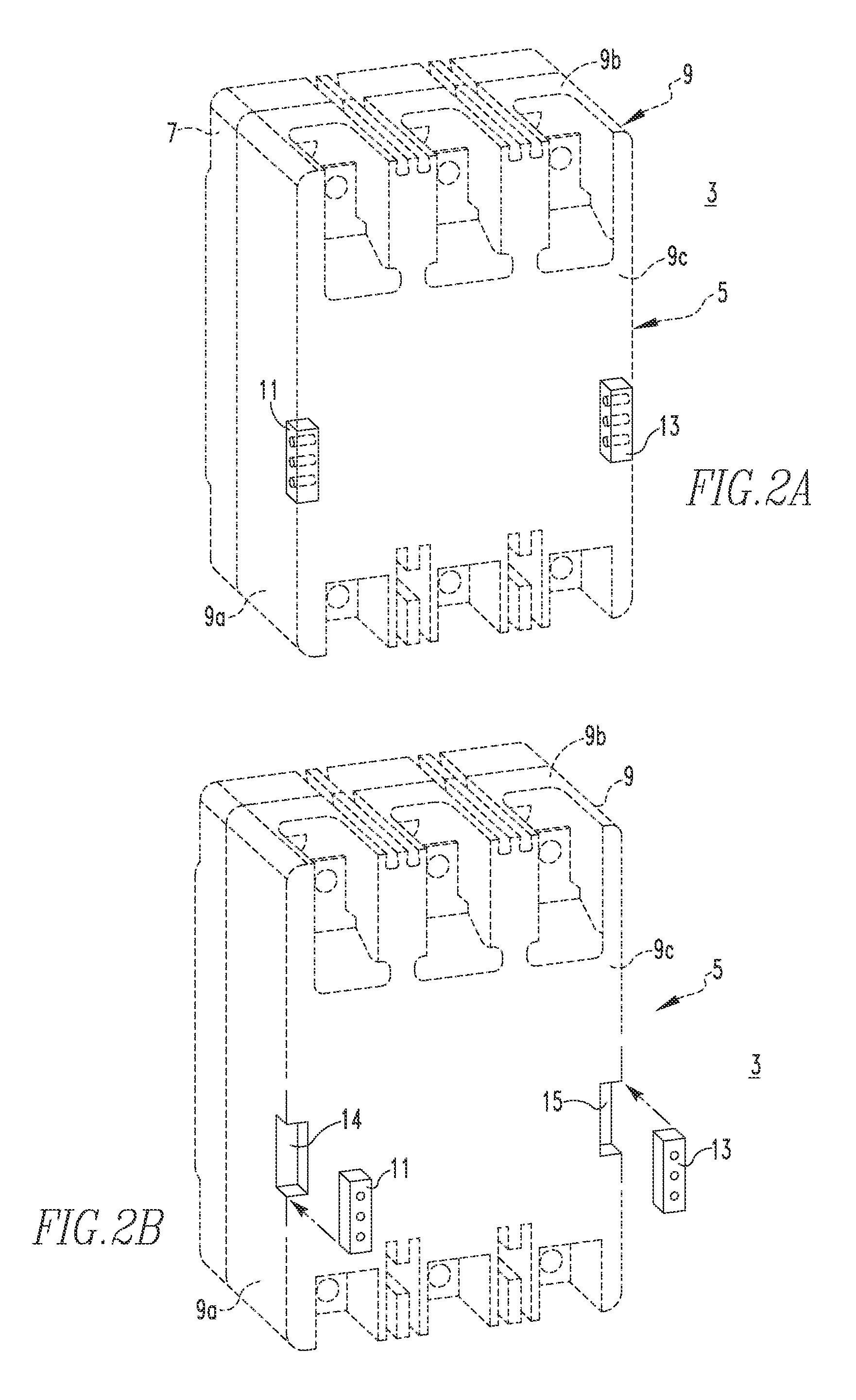
  • Molded case circuit breaker accessory wiring improvement
  • Molded case circuit breaker accessory wiring improvement
  • Molded case circuit breaker accessory wiring improvement

Examples


Embodiment Construction

[0030]For purposes of illustration, embodiments of the disclosed concept will be shown and described as applied to low-voltage molded case circuit breakers, although it will become apparent that they also could be applied to a wide variety of electrical switching apparatus (e.g., without limitation, circuit switching devices and other circuit interrupters, such as contactors, motor starters, motor controllers and other load controllers) other than low-voltage molded case circuit breakers and other than low-voltage electrical switching apparatus.

[0031]Directional phrases used herein, such as, for example, left, right, clockwise, counterclockwise, top, bottom and derivatives thereof, relate to the orientation of the elements shown in the drawings and are not limiting upon the claims unless expressly recited therein.

[0032]As employed herein, the terms “connector” and “connector assembly” refer to any known or suitable component or assembly, respectively, that is structured to accept on...


PUM


Abstract

The disclosed concept relates to electrical switching apparatus, such as, but not limited to, molded case circuit breakers, and more particularly, to a connector assembly for mechanically and electrically connecting the accessory components housed within the electrical switching apparatus to equipment located outside of the electrical switching apparatus.

Description

BACKGROUND[0001]1. Field[0002]The disclosed concept relates generally to electrical switching apparatus and, more particularly, circuit interrupters, such as circuit breakers. The disclosed concept also relates to electrical switching apparatus accessory components, such as, for example, shunt trip and under voltage release devices.[0003]2. Background Information[0004]Electrical switching apparatus are often equipped with accessory components such as, for example and without limitation, shunt trip devices and under voltage release (UVR) devices. Such devices can be employed in a variety of ways to initiate a change in status of the apparatus such as, for example, to trip open separable contacts of the apparatus in response to an electrical fault condition (e.g., without limitation, current overload, short circuit or abnormal voltage) or other external condition.[0005]Electrical switching apparatus include, for example, circuit switching devices, circuit interrupters, such as circuit...

Claims


Application Information

Patent Timeline
Patent Type & Authority Patents(United States)
IPC IPC(8): H01H9/54H01H71/08H01R13/502H01H1/06H01H45/02
CPCH01H9/54H01H1/06H01H45/02H01H71/08H01R13/502H01H2071/086H01H2223/00
Inventor LAGREE, JAMES LEOTERHORST, BRUCE RICHARD
Owner EATON INTELLIGENT POWER LTD
Learn More