Method and apparatus for retaining a valve to a cement head

a cement head and valve body technology, applied in the field of apparatus for retaining elevated objects, can solve the problems of insufficient retention of elevated objects, inability to prevent said elevated objects from falling, injuring personnel or damaging property, and lifted objects inadvertently making physical contact with the plug valve, etc., to achieve quick and efficient secure/tightening, significant improvement

Active Publication Date: 2016-11-08
FRANKS INT
View PDF17 Cites 0 Cited by
  • Summary
  • Abstract
  • Description
  • Claims
  • Application Information

AI Technical Summary

Benefits of technology

[0009]A pouch-like harness member wraps around and supports a valve or other elevated object, and can be quickly and efficiently secured / tightened around said valve or other object using straps having hook and loop (Velcro®) fasteners. At least one sling or other cable member connected to said harness member can be efficiently secured to an adjacent cement head in order to provide positive retention should said valve become knocked loose, sheared or otherwise detached. In such an event, the retention assembly of the present invention prevents said valve from falling and injuring personnel or damaging property situated there below.
[0010]The retention assembly of the present invention is inexpensive, easy to use, and is significantly more effective than conventional connection systems (including, without limitation, whip-checks, tugger lines and / or conventional choker devices).

Problems solved by technology

Such conventional retention systems prevent said hose or conduit from dropping or detaching completely in the event said hose or conduit becomes damaged or inadvertently disconnected, such as when impacted by a foreign object.
However, such conventional retention systems do not adequately retain elevated objects (particularly heavy objects), and do not prevent said elevated objects from falling and injuring personnel or damaging property.
As a result, there is frequently a risk that such a lifted object will inadvertently make physical contact with a plug valve, shearing it away from a main cement head assembly.
Although a cable or other line may connect said cement valve to a cement head assembly, such conventional connection means do not provide adequate protection to fully secure such valve and prevent it from falling on personnel or equipment situated there below.

Method used


Image

  • Method and apparatus for retaining a valve to a cement head
  • Method and apparatus for retaining a valve to a cement head
  • Method and apparatus for retaining a valve to a cement head

Examples


Embodiment Construction

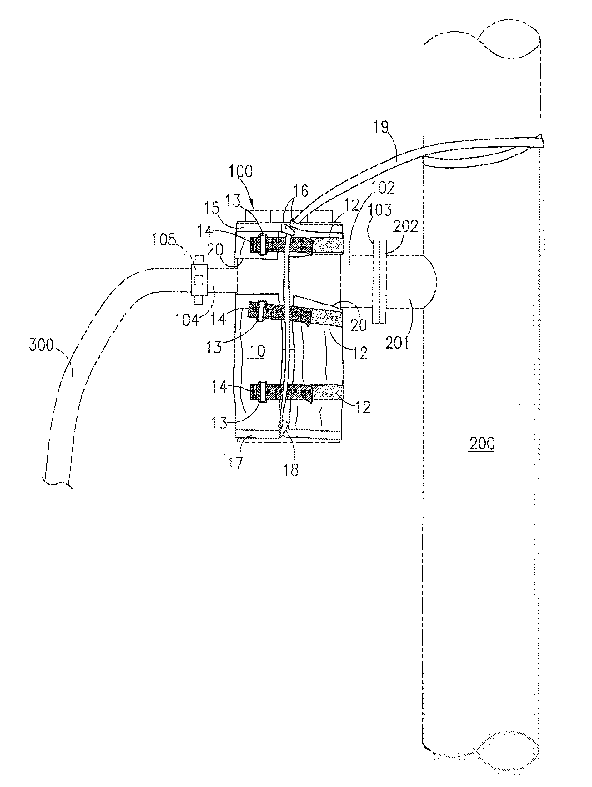
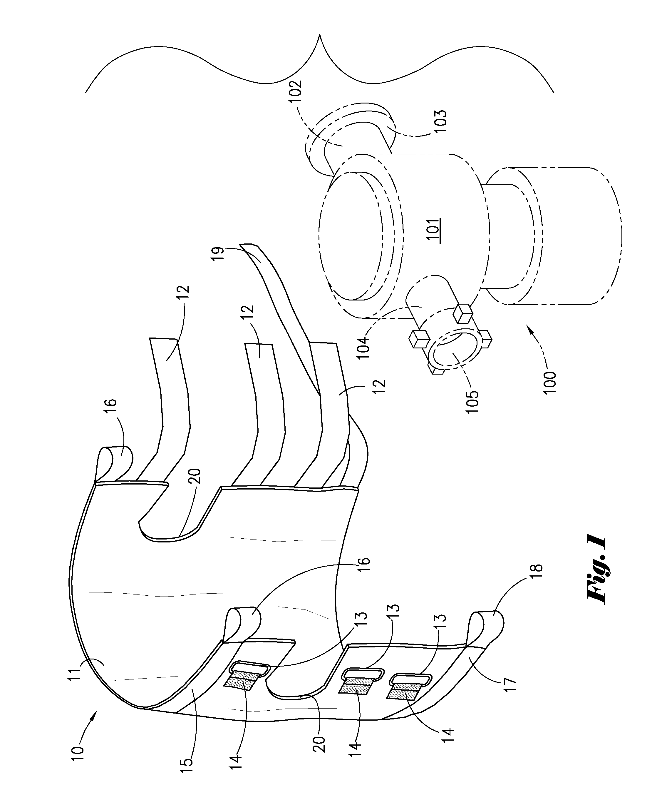
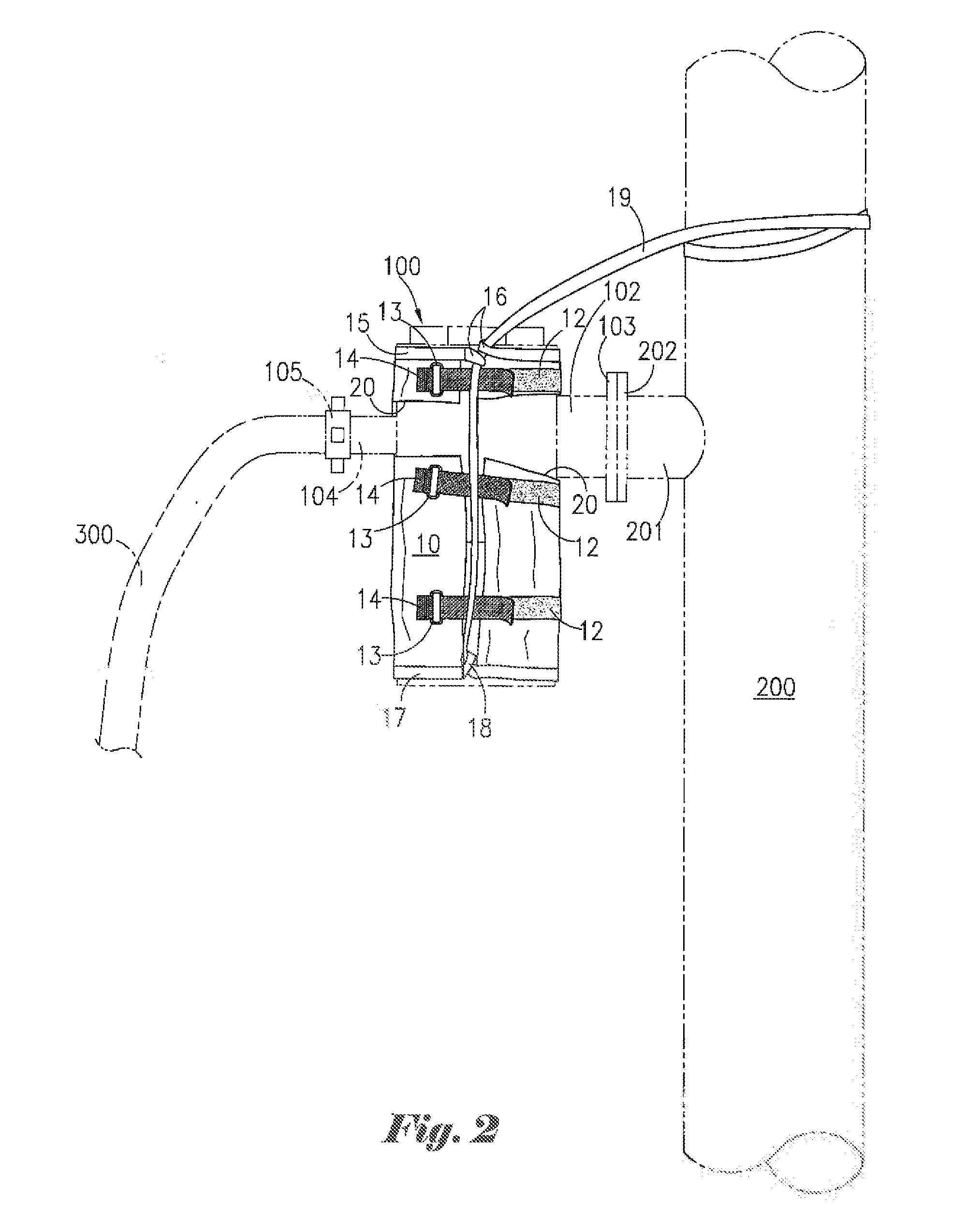
[0014]FIG. 1 depicts a side perspective view of retention assembly 10 of the present invention together with a conventional cement plug valve 100. By way of illustration, but not limitation, retention assembly 10 of the present invention is described herein as being used in connection with cement plug valve 100. However, it is to be observed that retention assembly 10 of the present invention can be used to retain and secure any number of other elevated objects or equipment other than said cement plug valve 100.

[0015]As depicted herein, said cement plug valve 100 comprises body section 101, as well as lateral conduit lines 102 and 104. Lateral conduit line 102 can be equipped with connection flange 103 for attaching valve 100 to an input port of a cement head (not depicted in FIG. 1). Lateral conduit line 104 can similarly be equipped with a hammer union connection 105 for attaching a cement hose, chicksan or other flow conduit to valve 100. It is to be observed that the specific co...


PUM


Abstract

An apparatus for retaining and securing elevated objects such as cement valves. A harness member is wrapped around the outer surface of an elevated object, and adjustable straps are tightened to secure the harness member in place. An elongate sling member, attached the harness member, is securely attached to a cement head assembly or other nearby support structure. The apparatus provides positive retention should an elevated object become detached, thereby preventing the object from falling and injuring personnel or damaging property.

Description

BACKGROUND OF THE INVENTION[0001]1. Field of the Invention[0002]The present invention pertains to an apparatus for retaining and securing elevated objects. More particularly, the present invention pertains to an apparatus for attaching elevated equipment including, without limitation, cement plug valves, to a nearby support structure.[0003]2. Brief Description of the Prior Art[0004]Existing hose retention systems include conventional whip-check and / or choker devices that are typically attached between hoses and other equipment. Such existing retention systems typically comprise cables, ropes or other lines that secure a hose or other conduit to a nearby tank or other object to which said hose or conduit is connected. Such conventional retention systems prevent said hose or conduit from dropping or detaching completely in the event said hose or conduit becomes damaged or inadvertently disconnected, such as when impacted by a foreign object. However, such conventional retention system...

Claims


Application Information

Patent Timeline
Patent Type & Authority Patents(United States)
IPC IPC(8): E21B33/16F16L3/137E21B41/00F16L3/00F16M13/02
CPCE21B33/16E21B41/00E21B41/0021F16L3/00F16L3/137F16M13/02F16L41/08F16L55/005
Inventor ROBICHAUX, RON D.BROWN, BOBBY L.
Owner FRANKS INT
Why Eureka
Try Eureka