Embossing stamp and die plate holder for the embossing stamp

a technology of embossing stamps and die plates, which is applied in the field of embossing stamps, can solve the problems of high labor requirements in order to produce reliefs in documents/papers or photographs, large number of individual parts required which have to be assembled manually, and achieves the effect of compact structure and easy legibility

Active Publication Date: 2016-10-25
TRODAT GMBH
View PDF26 Cites 1 Cited by
  • Summary
  • Abstract
  • Description
  • Claims
  • Application Information

AI Technical Summary

Benefits of technology

The invention aims to provide an embossing stamp that is easier to use and manufacture. The stamp has a modular design with lightweight components that improve operator comfort and stability. The use of panels and half-shells simplifies manufacture and reduces the need for additional cross-connections. The embossing stamp is constructed from a metal panel, carbon panel, or aluminum panel which adds rigidity and prevents deformation. Overall, this design improves the quality and efficiency of the embossing process.

Problems solved by technology

The disadvantage here is that the design / dimensions of the operating device mean that both downwardly directed forces P1 and P2 are of the same magnitude, and thus a very high effort is required in order to produce a relief in a document / paper or photograph.
The disadvantage of such a solution is that the manufacturing costs are very high since a lot of individual parts have to be assembled together.
The disadvantage in this case is that with a construction of this type, again a very large number of individual parts are required which have to be assembled manually.
This means that manufacturing requirements are very high, and so very high manufacturing costs are also unavoidable.
A further substantial disadvantage is that the embossing stamp has to be provided with outwardly directed feet so that it can be placed upright since, because the side walls are thin and lamellar, the footprint area is only small.
Moreover, the outwardly projecting feet mean that the embossing stamp is very user-unfriendly because when it is held in the hand, the feet get in the way.
Because of the large forces involved in an embossing procedure, screw connections frequently loosen or undo and the structure becomes very wobbly.
In addition, constructing all the parts from metal means that the embossing stamp is very heavy, making handling of it more difficult.
However, the disadvantage is that it is not possible to stand the plier seal upright on a flat surface.
Thus, it is also not possible to carry out what is known as tabletop embossing, where the embossing stamp is placed on a table and the user presses the lever downwards.
The disadvantage here is that fastening of the die plate holder in the retaining device is not optimal.
A further disadvantage is that by disposing the die plate carrier in the base unit, it is not secured against slipping out.

Method used


Image

  • Embossing stamp and die plate holder for the embossing stamp
  • Embossing stamp and die plate holder for the embossing stamp
  • Embossing stamp and die plate holder for the embossing stamp

Examples


Embodiment Construction

[0066]Firstly, it should be stated that in the various embodiments, identical parts are provided with identical reference numerals, whereby the disclosures in the description as a whole can be applied mutatis mutandis to identical parts with identical reference numerals. In addition, the positional information contained in the description, such as top, bottom, side, etc., for example, refer to the figure being described and shown at the time and should be applied mutatis mutandis to a new position when the position is changed.

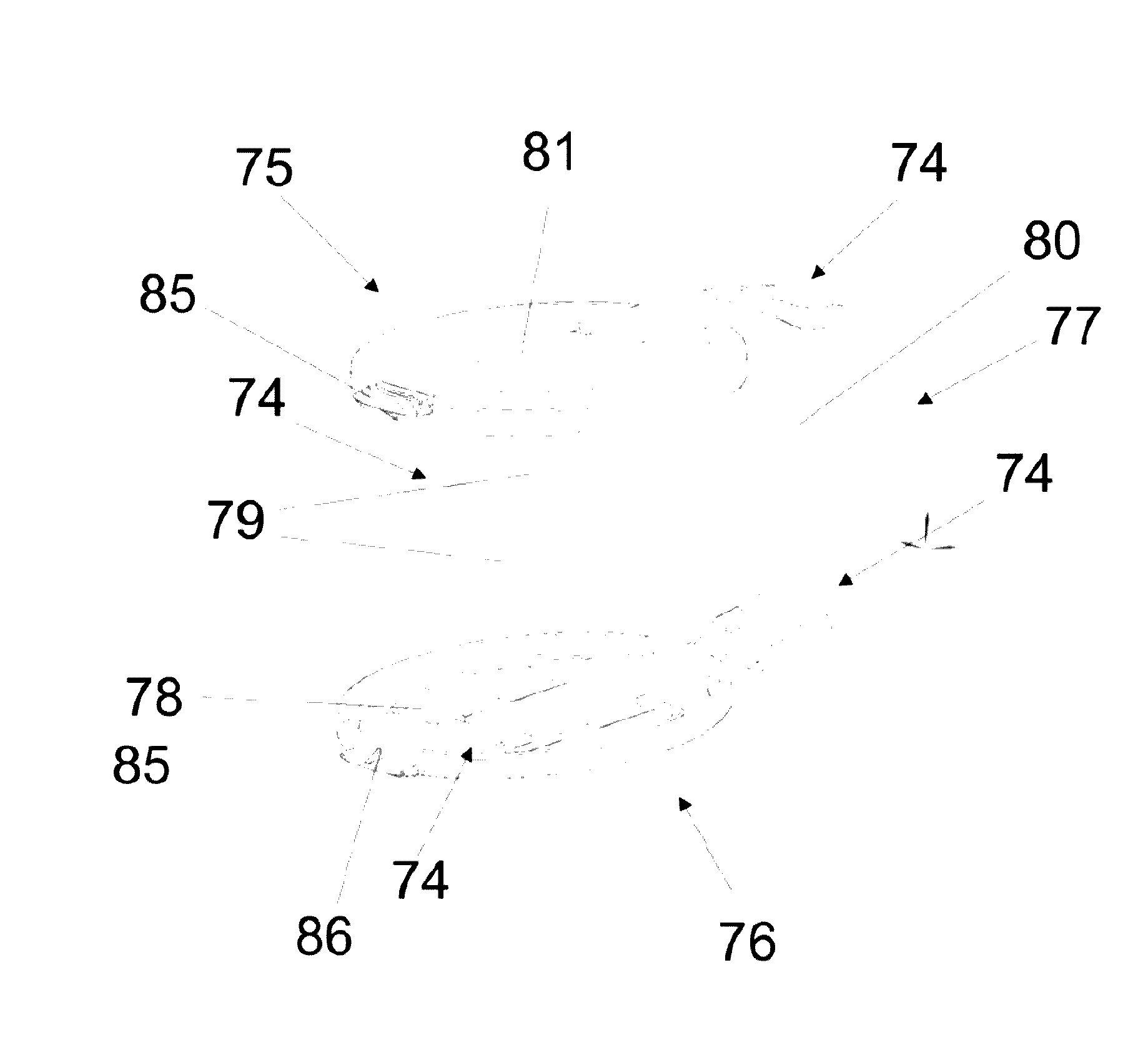
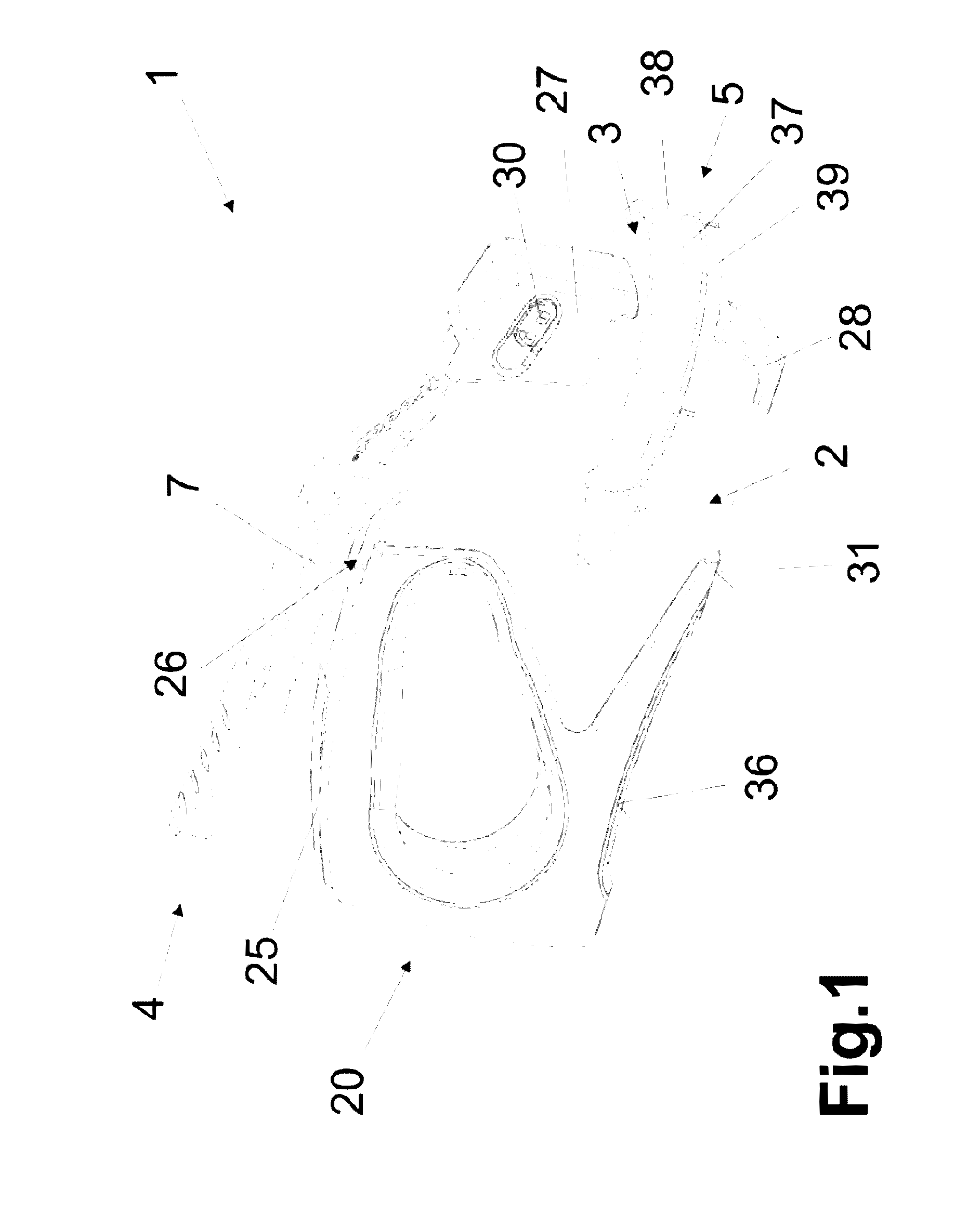
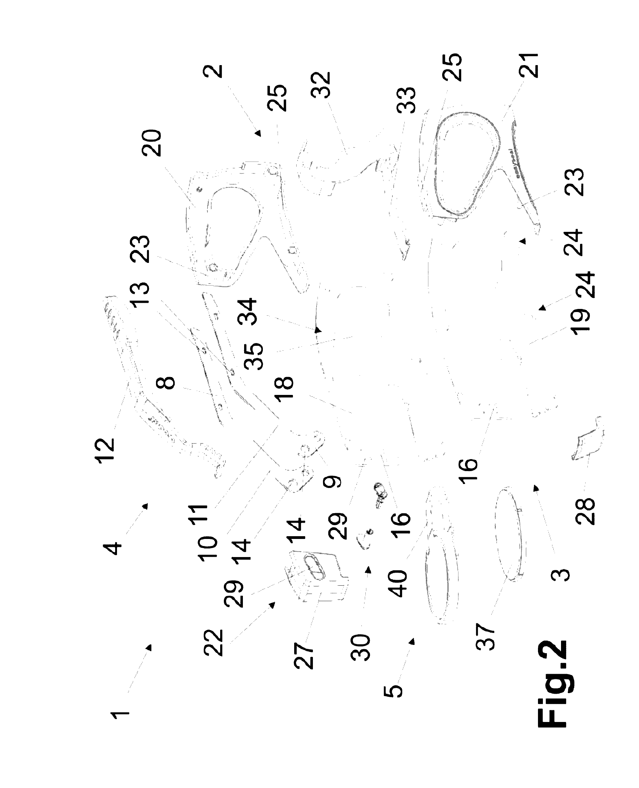
[0067]FIGS. 1 to 3 show an embossing stamp 1, or what is known as a plier seal, for the production of relief depictions (not shown) on documents, papers or photographs, wherein the relief is formed without colour. In order to make it possible to form reliefs, the embossing stamp 1 has to exert high pressures on the document, paper or photograph etc.; and so this has to be constructed in a very robust manner. In the prior art, embossing stamps 1 are always const...


PUM


Abstract

The invention describes an embossing stamp comprising at least a base unit in which a retaining device is disposed on one side to retain a die plate holder and an operating device is disposed on a further side. The operating device is constructed such that it directly or indirectly acts on the retaining device, wherein a pivot of the operating device is disposed in the base unit. The base unit and / or the operating device are modular in construction, wherein the side walls are at least partially formed by panels which are positioned with respect to each other and fastened via half-shells and / or connecting means.

Description

CROSS-REFERENCE TO RELATED APPLICATIONS[0001]The present application is a divisional of U.S. patent application Ser. No. 14 / 258,682 filed Apr. 22, 2014, which claims priority from Austrian Patent Application No. A 341 / 2013, filed Apr. 23, 2013, all of which are hereby incorporated herein by reference.BACKGROUND OF THE INVENTION[0002]The invention relates to an embossing stamp comprising a base unit in which a retaining device is disposed on one side and an operating device is disposed on a further side, and the operating device is constructed such that it directly or indirectly acts on the retaining device, wherein a pivot of the operating device is disposed in the base unit, and a die plate holder comprising an upper and lower embossing plate retainer which are connected together via a guide strip.[0003]Embossing stamps, also known as plier seals, are known and used for the production of a relief without colour on documents / papers or photographs. The document / paper or photograph is...

Claims


Application Information

Patent Timeline
Patent Type & Authority Patents(United States)
IPC IPC(8): B44B5/02B44B5/00B41K3/36
CPCB44B5/0085B44B5/0023B44B5/0052B41K3/36B44B5/02B44B5/0038
Inventor RIEGLER, KONRADLINDNER, HELMUT
Owner TRODAT GMBH
Why Eureka
Try Eureka