
Arrangement, a loop-shaped support, a prosthetic heart valve and a method of repairing or replacing a native heart valve

a heart valve and loop support technology, applied in the field of medical devices and methods, can solve the problems of incomplete coaptation, less effective heart valve, and potentially severe consequences for patients, and achieve the effect of improving stability

Active Publication Date: 2016-10-25
MEDTENTIA INT LTD OY
View PDF9 Cites 117 Cited by
  • Summary
  • Abstract
  • Description
  • Claims
  • Application Information

AI Technical Summary

Benefits of technology

This patent is about a way to prevent a new heart valve from leaking or causing regurgitation. They do this by using a loop-shaped support and a prosthetic heart valve that can be minimally invasive and percutaneously replaced or repaired. This allows for a safer and less invasive way to treat heart valve issues.

Problems solved by technology

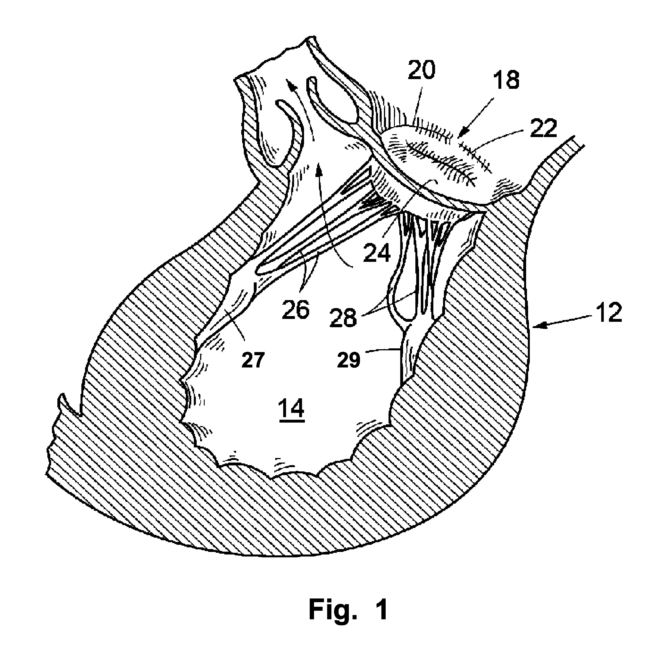
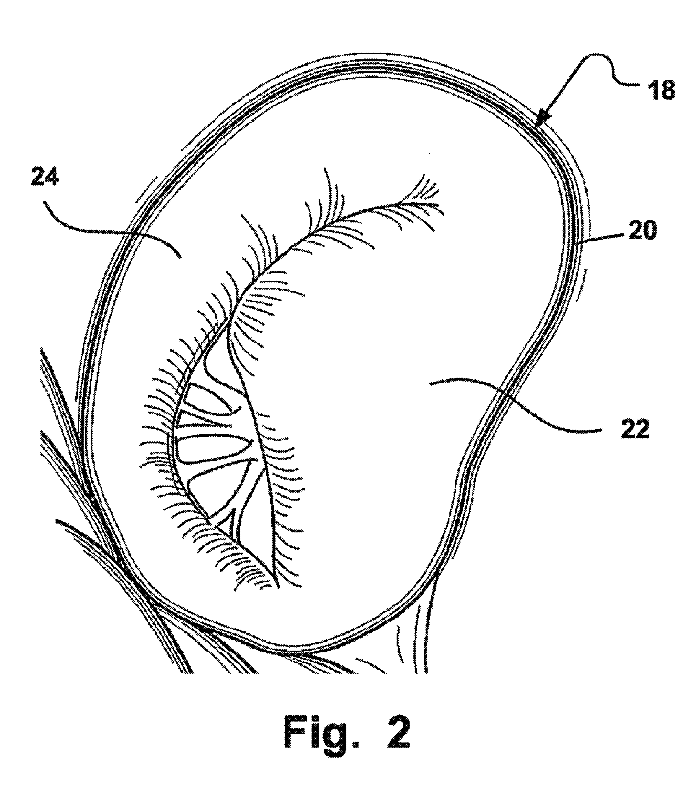
However, for some individuals the closure is not complete, which results in regurgitation, also called valvular insufficiency, i.e. a back flow of blood to the left atrium and potentially increasing blood pressure in pulmonary circulation making the heart less effective and with potentially severe consequences for the patient. FIG. 2 illustrates a mitral valve 18, in which the leaflets 22, 24 do not close properly.
Another possibility is that the leaflet is ruptured, most commonly at an edge of a leaflet, resulting in an incomplete coaptation.
Similar problems may arise in other native heart valves, such as in an aortic valve, in a pulmonic valve or in a tricuspid valve.
However, it may be difficult to fit the prosthetic heart valve tightly to the native heart valve and thus, there may be a back-flow or leakage between the annulus or other surrounding valve tissue and the prosthetic heart valve.

Method used


Image

  • Arrangement, a loop-shaped support, a prosthetic heart valve and a method of repairing or replacing a native heart valve
  • Arrangement, a loop-shaped support, a prosthetic heart valve and a method of repairing or replacing a native heart valve
  • Arrangement, a loop-shaped support, a prosthetic heart valve and a method of repairing or replacing a native heart valve

Examples


Embodiment Construction

[0044]Specific embodiments of the disclosure will now be described with reference to the accompanying drawings. This disclosure may, however, be embodied in many different forms and should not be construed as limited to the embodiments set forth herein; rather, these embodiments are provided so that this disclosure will be thorough and complete, and will fully convey the scope of the invention to those skilled in the art. The terminology used in the detailed description of the embodiments illustrated in the accompanying drawings is not intended to be limiting of the disclosure. In the drawings, like numbers refer to like elements.

[0045]The following description focuses on an embodiment of the present disclosure applicable to a native heart valve and in particular to a mitral valve. However, it will be appreciated that the disclosure is not limited to this application but may be applied to many other heart valves including for example an aortic valve, a pulmonic valve or a tricuspid ...


PUM


Abstract

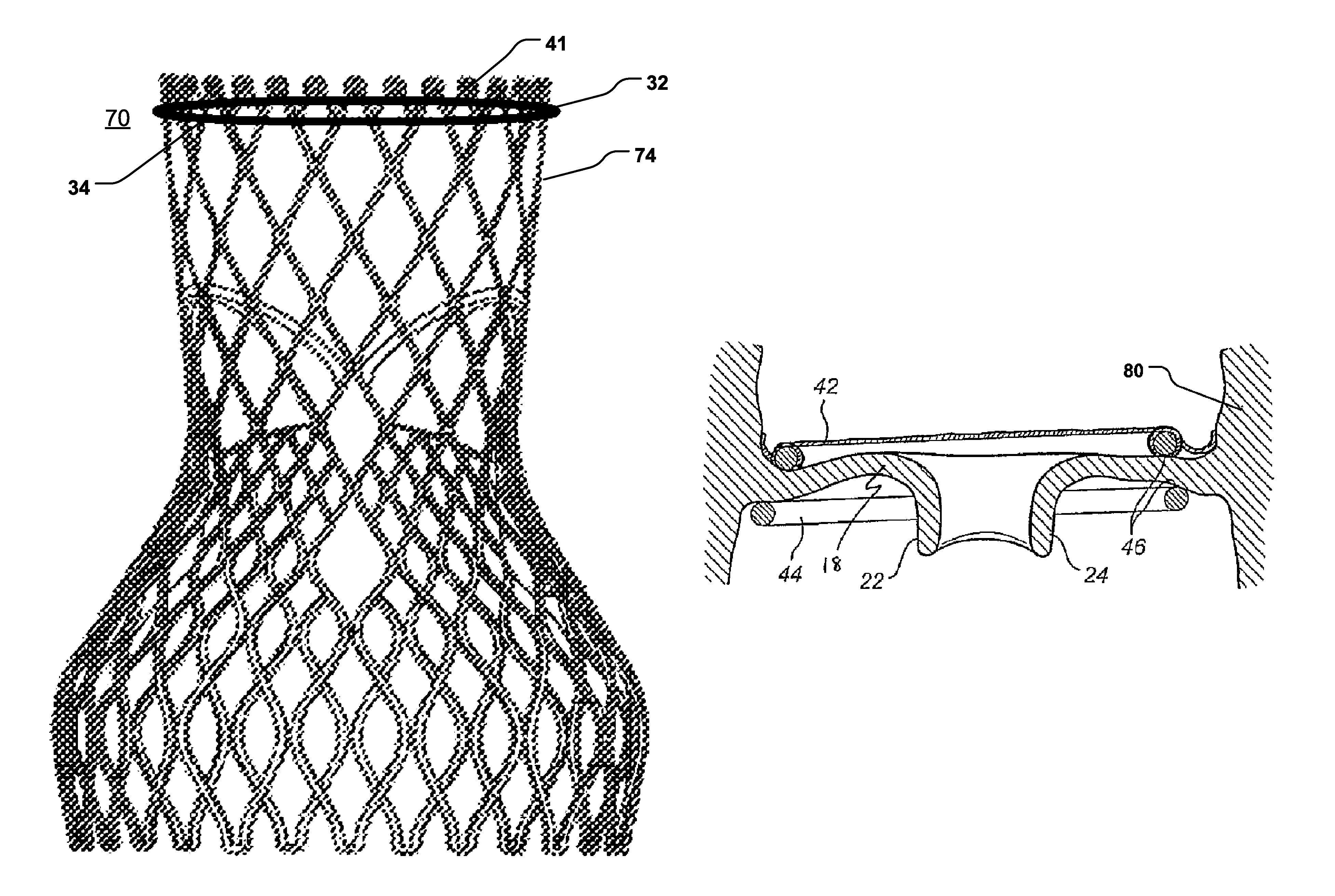
The present disclosure relates to an arrangement, a loop-shaped support, a prosthetic heart valve and a method of repairing or replacing a native heart valve. With the method or the arrangement, leakage or regurgitation between a prosthetic heart valve and the surrounding valve tissue is prevented. In one embodiment, an arrangement for replacement or repair of a native heart valve is provided, which comprises a loop-shaped support (41) and a prosthetic heart valve (70) and wherein an outer segment (32) of the loop-shaped support (41) is positionable towards surrounding valve tissue of a native heart valve and wherein an outer surface (74) of the prosthetic heart valve (70) is positionable towards an inner segment (34) of the loop-shaped support (41) so as to prevent paravalvular leakage or regurgitation between the prosthetic heart valve (70) and the surrounding valve tissue of the native heart valve.

Description

RELATED APPLICATIONS[0001]This application is the U.S. National Phase of and claims priority to International Patent Application No. PCT / EP2013 / 051366, International Filing Date Jan. 24, 2013, entitled An Arrangement, A Loop-Shaped Support, A Prosthetic Heart Valve And A Method Of Repairing Or Replacing A Native Heart Valve, which claims benefit of European Application No. EP12152348.4, filed Jan. 24, 2012 entitled An Arrangement, A Loop-Shaped Support, A Prosthetic Heart Valve And A Method Of Repairing Or Replacing A Native Heart Valve; and U.S. Provisional Application Ser. No. 61 / 590,715, filed Jan. 25, 2012 entitled An Arrangement, A Loop-Shaped Support, A Prosthetic Heart Valve And A Method Of Repairing Or Replacing A Native Heart Valve; all of which are incorporated herein by reference in their entireties.BACKGROUND OF THE INVENTION[0002]1. Field of the Invention[0003]This disclosure pertains in general to the field of medical devices and methods. More particularly, the disclos...

Claims


Application Information

Patent Timeline
Patent Type & Authority Patents(United States)
IPC IPC(8): A61F2/24
CPCA61F2/2409A61F2/2418A61F2/2427A61F2/2442A61F2/2445A61F2/2466A61F2230/008A61F2230/0013A61F2230/0091A61F2250/006
Inventor KERANEN, OLLI
Owner MEDTENTIA INT LTD OY
Learn More