High pressure isolated latching safety switch device

a technology of latching safety switch and high pressure, which is applied in the direction of ammunition fuzes, electrical appliances, weapons, etc., can solve the problems of device not easily implementable to a 120 mm, unspun, and inability to be easily implemented

Active Publication Date: 2016-10-18
UNITED STATES OF AMERICA THE AS REPRESENTED BY THE SEC OF THE ARMY
View PDF29 Cites 0 Cited by
  • Summary
  • Abstract
  • Description
  • Claims
  • Application Information

AI Technical Summary

Benefits of technology

[0009]It is a further object of the present invention to provide a switch to arm a munition upon launch, whereby such switch employs multiple sealing methods to protect the switch against leaking gas pressure into the munition, after the switch has first been actuated.

Problems solved by technology

This problem has existed since the added military requirement that fuzes must also have a second environmental safety that is unrelated to the primary safety.
Many of these devices are not easily implementable to a 120 mm, un-spun, tank munition, e.g. These ways of solving the problem are unsatisfactory because in terms of fuze safety, it has been decided that there needs to be a more robust second environment than commit to launch, e.g., whereas temperature, heat and spin, as mentioned are not easily implementable.

Method used


Image

  • High pressure isolated latching safety switch device
  • High pressure isolated latching safety switch device
  • High pressure isolated latching safety switch device

Examples


Embodiment Construction

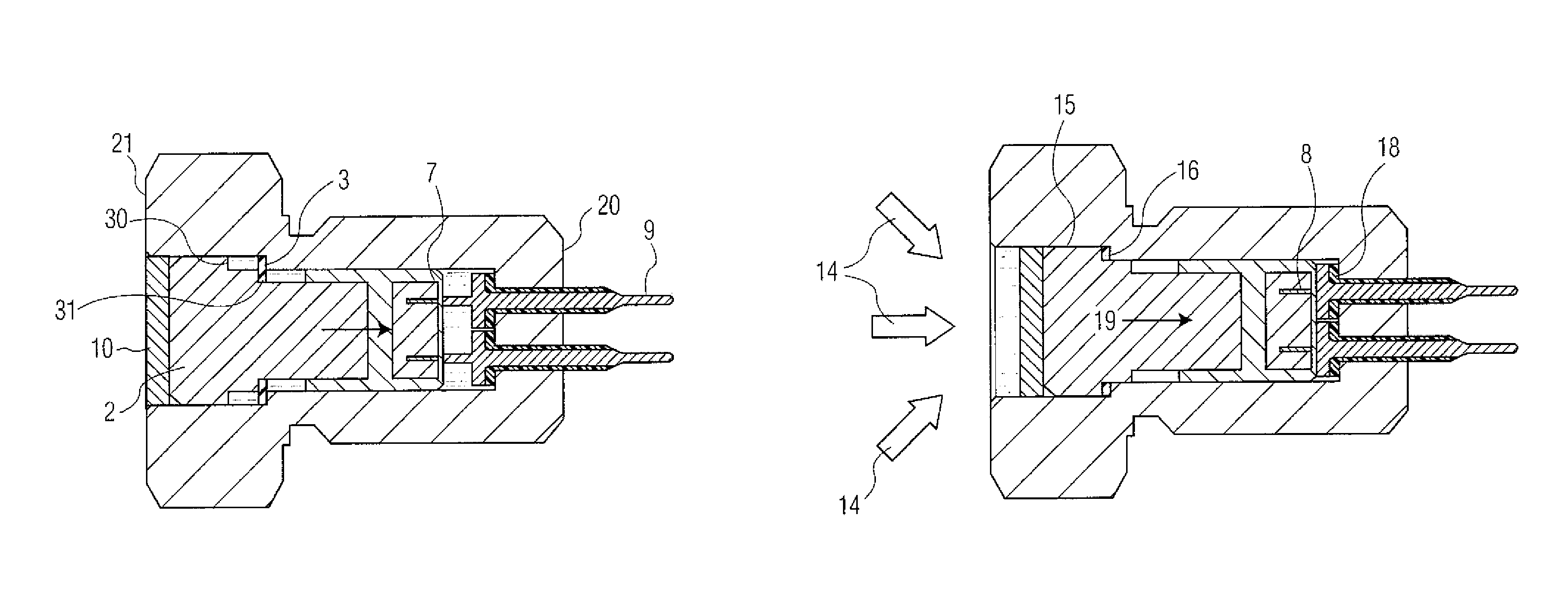
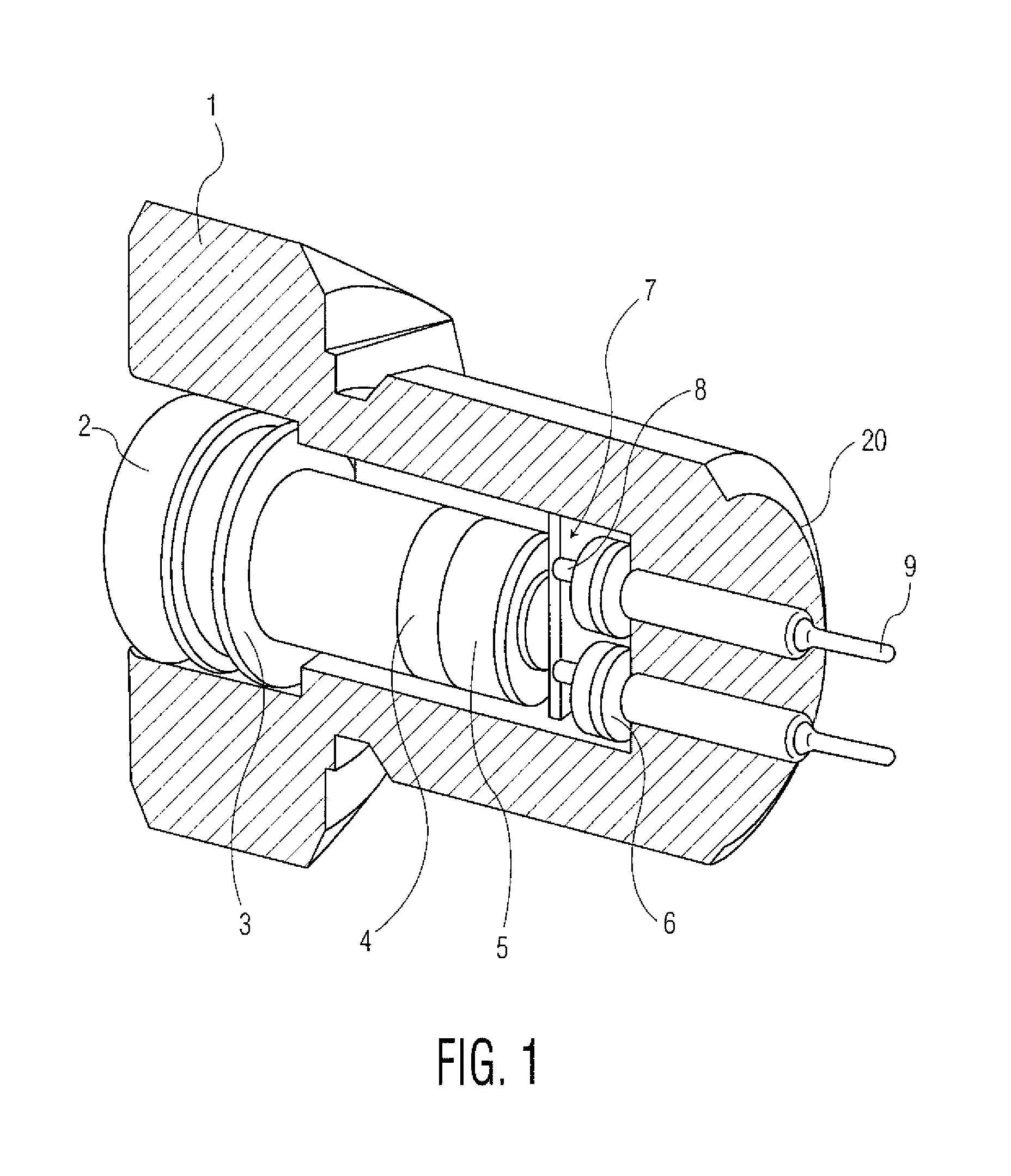
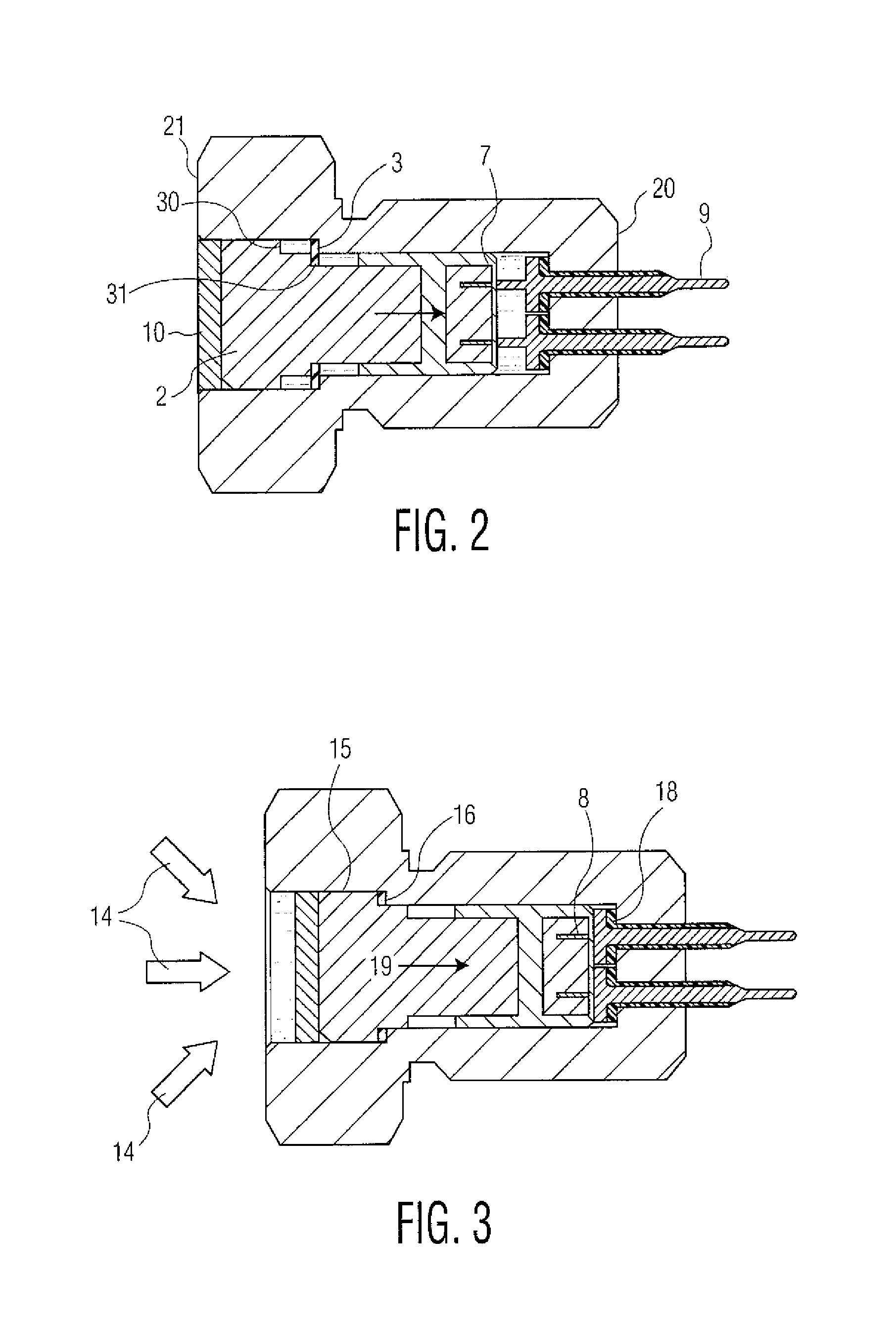
[0014]The design of the pressure switch is shown in FIG. 1. The components are designed such that there are no special machining operations, welding, or complicated assembly operations to manufacture this device. All of the internal components of the pressure switch lend themselves to be manufactured in a high production environment with the use of Swiss-type screw machines and plastic injection molding processes to keep production costs extremely low.

[0015]A hollow 17-4 stainless steel housing 1 contains all of the components of the proposed pressure switch, and provides a M12×1 internal thread means (not completely shown) of fastening this switch to a munition. The housing has a defined forward end 20, as well as a rear end 21 shown in FIG. 2. The piston 2 is made of 17-4 stainless steel and provides for conversion of gas pressure into linear motion for the switch to function. The piston has two forward shoulders (30, 31, shown in FIG. 2). An aluminum shear disc 3 at the forward m...


PUM


Abstract

A pressure switch is provided to arm a munition's fuze mechanism upon launch. The switch operation is based upon extreme gas pressures experienced during launch of the munition. The switch includes a piston contained in a housing. The piston translates due to launch pressures. The piston translation then causes a copper puck component to contact nearby electrical stab pins, to close a circuit. The closed circuit is then used to electrically arm the fuze mechanism.

Description

CROSS REFERENCE TO RELATED APPLICATIONS[0001]This application claims benefit under 35 USC§119 (e) from provisional application Ser. No. 62 / 046,429 filed Sep. 5, 2014, having same title and same inventor names, the entire file wrapper contents of which are hereby incorporated by reference as though fully set forth.U.S. GOVERNMENT INTEREST[0002]The inventions described herein may be made, used, or licensed by or for the U.S. Government for U.S. Government purposes.BACKGROUND OF INVENTION[0003]This invention solves the problem of a current lack of products available through the commercial market to provide a reliable, ultra high pressure, latching pressure switch to act as a second environment safety for ammunition fuzing systems. This problem has existed since the added military requirement that fuzes must also have a second environmental safety that is unrelated to the primary safety.[0004]Old ways to provide a second safety include techniques such as a commit to launch function. In ...

Claims


Application Information

Patent Timeline
Patent Type & Authority Patents(United States)
IPC IPC(8): F42B3/18F42C15/32H01H35/26F42C5/00
CPCF42C5/00F42C15/32H01H35/26H01H35/38
Inventor CAHAYLA, JASONSUNDERLAND, JESSE
Owner UNITED STATES OF AMERICA THE AS REPRESENTED BY THE SEC OF THE ARMY
Why Eureka
Try Eureka