
Fastening device for fixing a cable

a technology for fixing devices and cables, which is applied in the direction of fastening means, electric/fluid circuits, vehicle components, etc., can solve the problems of high level of expenditure, high level of assembly and testing expenditure, and high level of expenditure on assembly and testing, so as to improve the fixing of cables and improve the mounting of at least one cabl

Active Publication Date: 2016-09-13
CONTINENTAL TEVES AG & CO OHG
View PDF24 Cites 3 Cited by
  • Summary
  • Abstract
  • Description
  • Claims
  • Application Information

AI Technical Summary

Benefits of technology

[0006]An aspect of the invention proposes a fastening device for fixing at least one cable, which fastening device is relatively inexpensive and / or reliable and / or allows improved or simple mounting of at least one cable and / or improves the fixing of the cable with respect to the flexible and, in this case, in particular defined orientation of the cable.
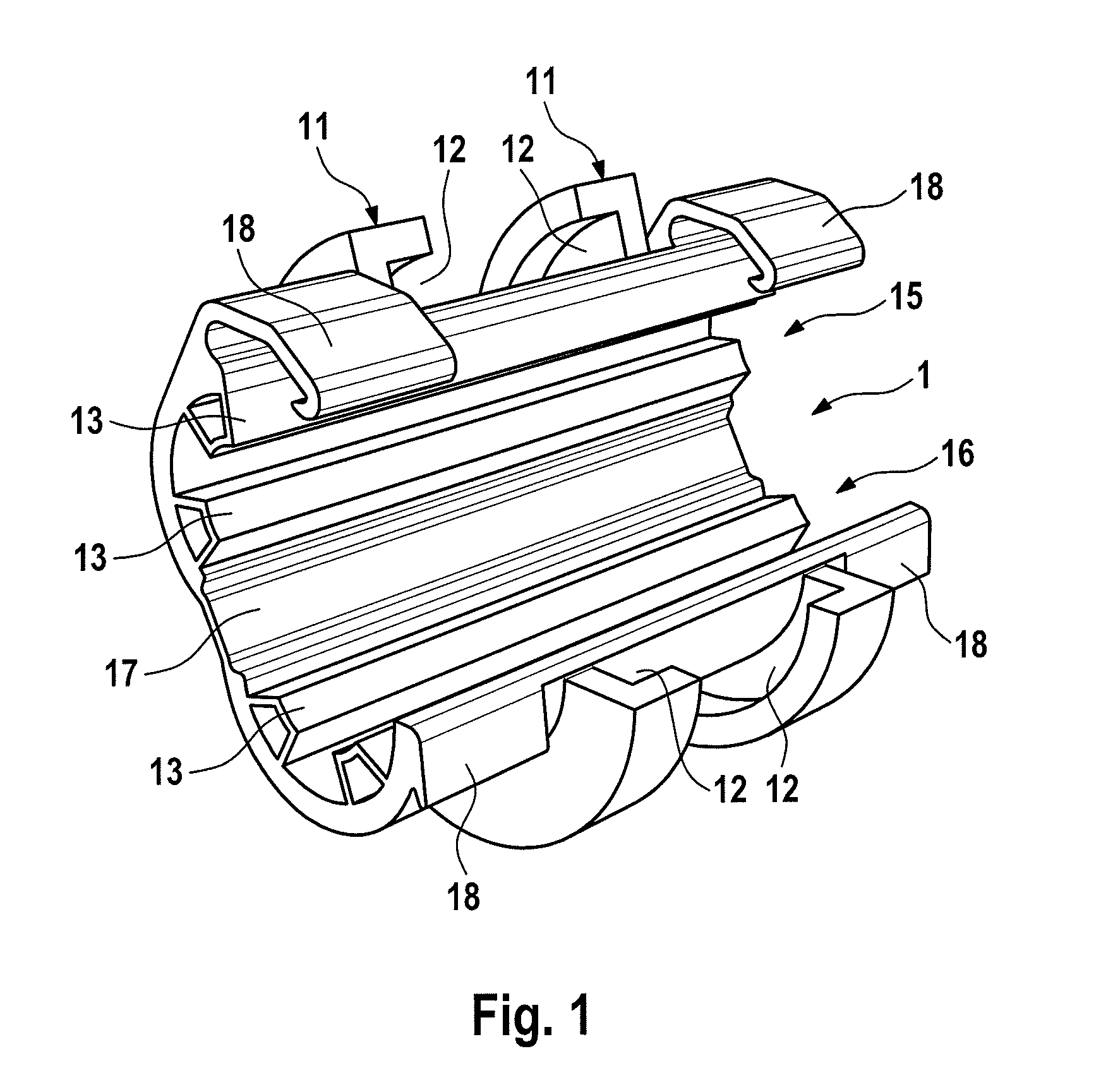
[0016]The mount, comprising the two grooves, and also the guide element which is mounted in this mount are expediently designed such that relative movements along the curvature or the circumferential line of the casing surface of the clip between the clip itself and the fixing element are possible.
[0017]The inside diameter of the space spanned by the retaining ribs of the clip is preferably somewhat smaller than the outside diameter of the cable or flexible supply line which is to be received and clamped. Owing to the mechanical stress or force-fitting clamping generated as a result, a clamping action or an interlocking connection between the cable and retaining ribs is generated in particular, wherein the cable and retaining ribs are each slightly deformed. This prevents an axial relative movement or displacement between the cable and the clip.

Problems solved by technology

This involves a high level of expenditure on assembly and testing and therefore expense.
This involves an additional manufacturing step and therefore expense.
Changes in the position on the cable or the flexible supply line are associated with a high level of expenditure.

Method used


Image

  • Fastening device for fixing a cable
  • Fastening device for fixing a cable
  • Fastening device for fixing a cable

Examples


Embodiment Construction

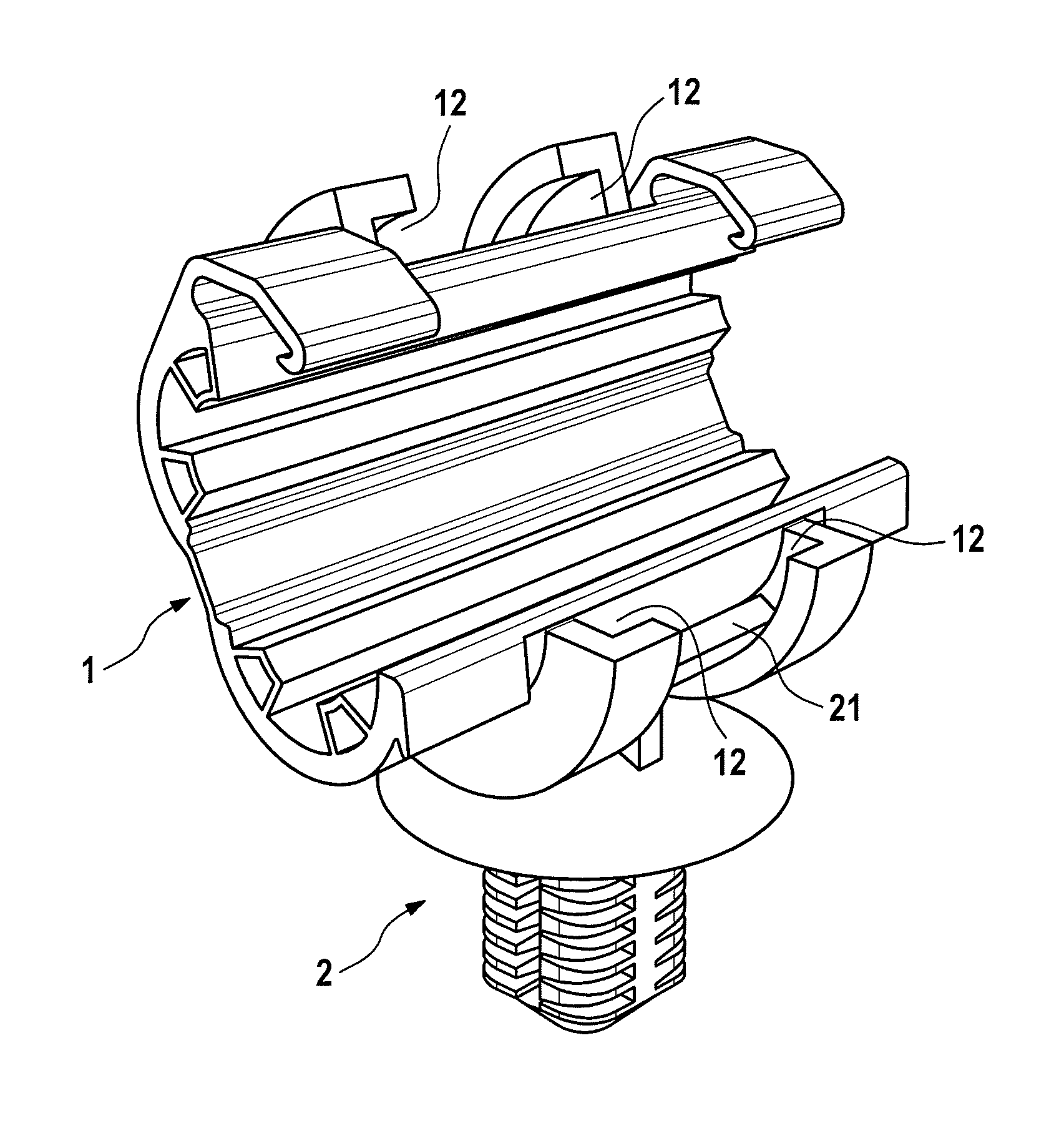
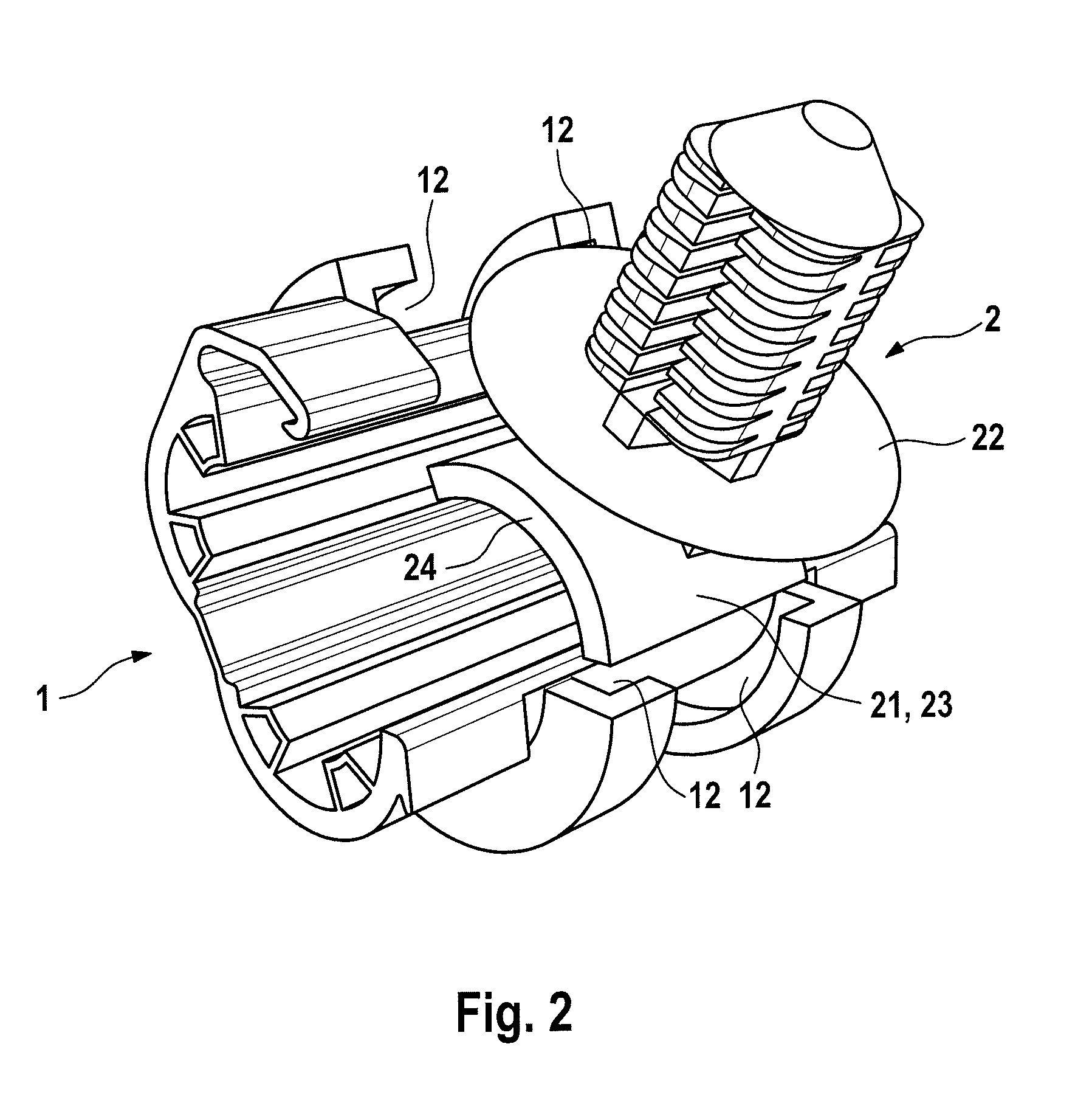
[0023]FIG. 1 shows the clip 1 which has a first and a second segment 15, 16, which segments are connected to one another by means of a film hinge 17 or an elastic web. The clip has internal retaining ribs 13 which are designed to receive and mount and clamp a cable. In accordance with the example, the retaining ribs are hollow and have a defined wall thickness, so that the retaining ribs can act on the cable with a defined or definable retaining force. The clip 1 has two grooves 12 which form a mount which is designed such that it mounts the guide element of the fixing element, see FIG. 2, with respect to the casing surface of the clip in a manner at least partially surrounding said guide element.

[0024]The mount 11, comprising the two grooves 12, and also the guide element which is mounted in this mount, see FIG. 2, are designed such that relative movements along the curvature or the circumferential line of the casing surface of the clip 1 between the clip itself and the fixing elem...


PUM


Abstract

Fastening device for fixing at least one cable, wherein the fastening device includes a clip for receiving and / or fixing a cable, wherein the clip is designed such that it can at least partially surround the cable and clamp the cable in a force-fitting and / or interlocking manner, and wherein the fastening device has a fixing element which includes a guide element and a retaining element, wherein the guide element is mechanically connected to the clip, and the retaining element is designed such that it allows the fastening device to be mounted in a fixed position, wherein the guide element is mounted in the clip in a mount which at least partially surrounds the clip in respect of its casing surface.

Description

CROSS REFERENCE TO RELATED APPLICATIONS[0001]This application is the U.S. National Phase Application of PCT / EP2013 / 063662, filed Jun. 28, 2013, which claims priority to German Patent Application No. 10 2012 013 210.7, filed Jul. 4, 2012 and German Patent Application No. 10 2012 224 173.6, filed Dec. 21, 2012, the contents of such applications being incorporated by reference herein.FIELD OF THE INVENTION[0002]The invention relates to a fastening device for fixing a cable.BACKGROUND OF THE INVENTION[0003]The technical problem on which the invention is based When laying cables or flexible supply lines in a route-bound manner in space, said cables or flexible supply lines have to be fastened at fixing points. This is done either by fixing means (so-called brackets) on the main structure, said fixing means receiving a cable or flexible supply line, or fixing means which are fitted to the cable or flexible supply line and are connected to the main structure by means of a joining method. R...

Claims


Application Information

Patent Timeline
Patent Type & Authority Patents(United States)
IPC IPC(8): F16B2/20F16L3/127F16L3/10H02G3/32H02G3/00B60R16/02F16L3/16F16L3/123
CPCF16L3/1075B60R16/0215F16L3/1025F16L3/1058F16L3/127F16L3/16H02G3/26H02G3/32F16B2/20F16L3/123B60R16/02
Inventor DENNER, TIMOMUSOLF, TOBIAS
Owner CONTINENTAL TEVES AG & CO OHG
Learn More