
Accessory for coordinate measuring machine

a technology for coordinate measuring machines and accessory parts, which is applied in the direction of mechanical measuring arrangements, instruments, measurement devices, etc., can solve the problems of incompatibility of arrangement with orientable measurement heads, programming and debugging associated software procedures to a higher level of complexity, and the task is particularly challenging

Active Publication Date: 2016-08-30
TESA SE
View PDF15 Cites 13 Cited by
  • Summary
  • Abstract
  • Description
  • Claims
  • Application Information

AI Technical Summary

Benefits of technology

This solution simplifies the programming of complex parts by ensuring consistent lighting and visual tracking of the probe, reducing errors and crashes, and facilitating automatic identification and type recognition of parts, while also preventing and analyzing potential crashes.

Problems solved by technology

Such arrangements are in general incompatible with the orientable measure heads that are conventionally employed in Coordinate Measuring Machines.
The increased possibilities of the CMM brings however programming and debugging of the associated software procedures to a higher level of complexity, in particular when one attempts to measure complex geometry with a machine having a large number of degrees of freedom, and automatic tool switching.
This task is especially challenging when the workpiece has hidden parts and large dimensions, such that the operator cannot easily appreciate visually the movements of the probe.
In such cases it is sometimes necessary to employ complex lighting system and even, move around the machine to follow the probe's movement, and even in some cases, climb on the machine table.
Despite all that, errors and crashes of the probe head are not exceptional, in particular during programming and debugging operations.

Method used


Image

  • Accessory for coordinate measuring machine
  • Accessory for coordinate measuring machine
  • Accessory for coordinate measuring machine

Examples


Embodiment Construction

[0019]In the following, the expression ‘lower’, ‘upper’, high′, and ‘low’ refer to the conventional orientation of the touch probes in CMM, namely to a disposition in which the probe is vertical and the workpiece is below the probe. This is not however a limiting feature of the invention, but rather a choice aiming at simplifying the description's language. It must be understood that the invention can be used with any arbitrary orientation in space.

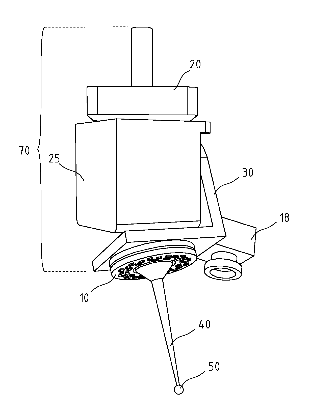
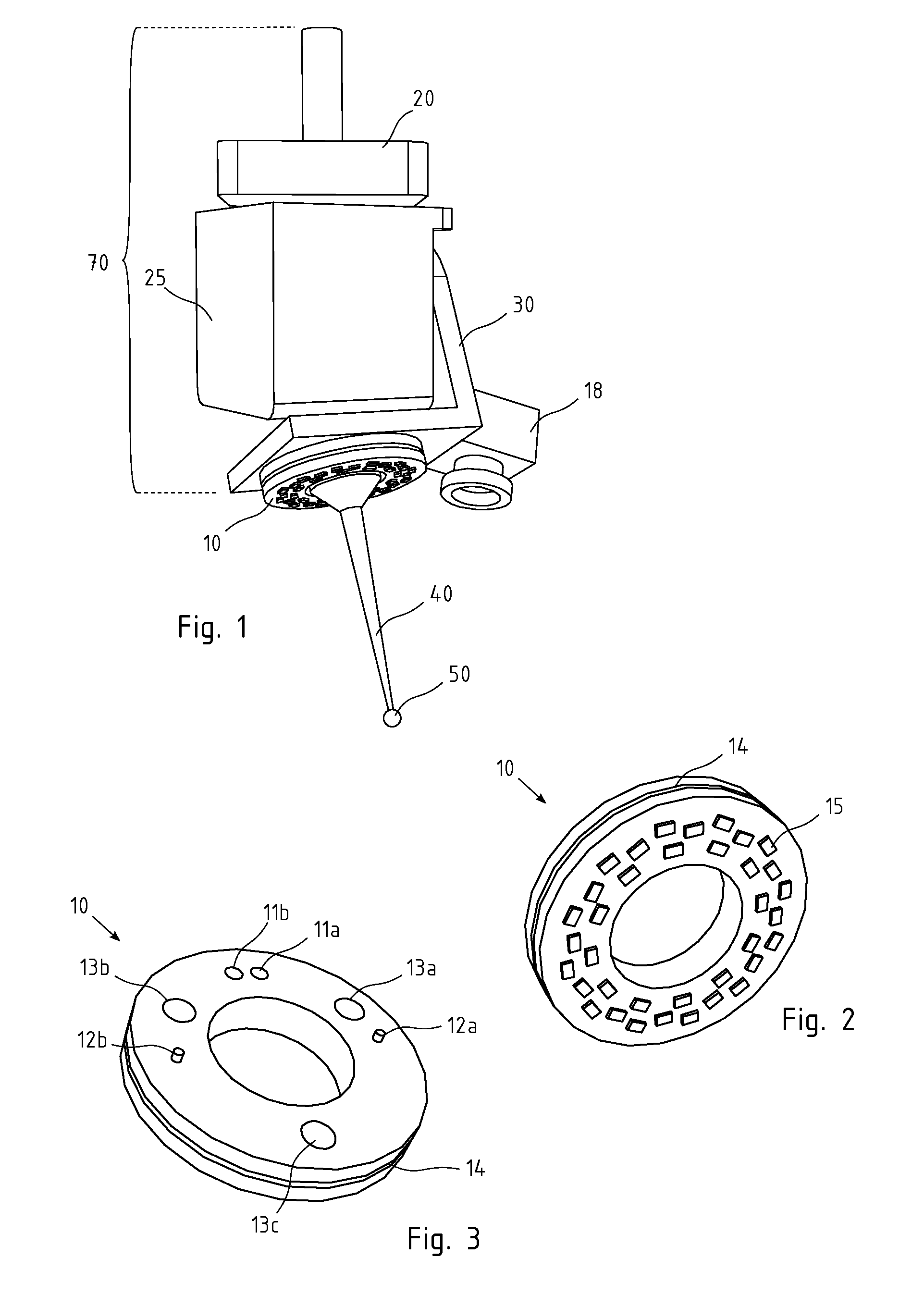
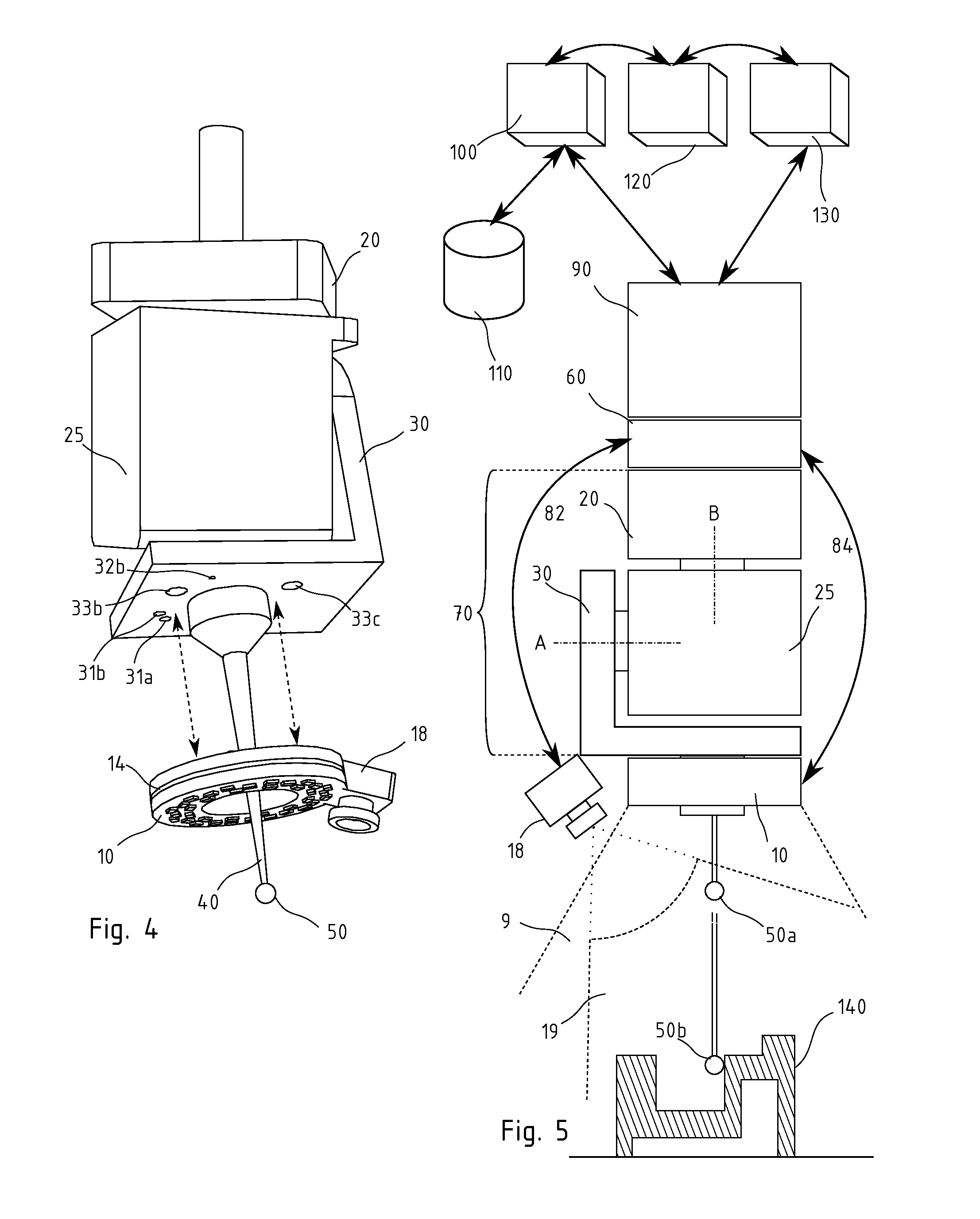
[0020]An embodiment of the invention will now be described with reference to FIGS. 1-3. The invention is associated, in this example, with an articulated head 70 that has the function of interface between a measure probe 40 and a tridimensional CMM (not represented). The measure head 70 has a support 20 that is connectable with the quill (often the ‘Z’ axis) of a CMM, and on the support are arranged a first rotor 25 and a second rotor 30 in series with the first one. The rotors 25 and 30 are rotatably arranged one after the other and are ...


PUM


Abstract

An accessory for an articulated head of a tridimensional coordinate measuring machine, machine tool or programmable manipulator. The invention includes a light source that is applicable adjacent to the measure probe in order to light selectively the measure point. The accessory can include an image capture device.

Description

FIELD OF THE INVENTION[0001]The present invention relates to an accessory combinable with a measuring head such as those employed in coordinate measuring machine (CMM), or else in machine tools, programmable manipulators or robots. In embodiments, the present invention relates to a light source connectable adjacent to the measure probe of a CMM and allowing selective lighting of the measure point. The accessory can likewise include an image capture device.DESCRIPTION OF RELATED ART[0002]Positioning systems arranged for measuring coordinates of mechanical workpieces are known in the art. Known variants of such measure systems employ touch probes, scanning probes, or vision probes.[0003]Coordinate measuring machines are often equipped with a variety of modular accessories, including orientable heads that allow choosing a suitable inclination for the measure probe, according to the measuring program that is desired, and the geometry of the workpieces under examination. Such orientable ...

Claims


Application Information

Patent Timeline
Patent Type & Authority Patents(United States)
IPC IPC(8): G01B11/14G01B21/04G01B5/012G01B11/00
CPCG01B11/005G01B21/04G01B21/047G01B5/012G01B11/007
Inventor KOCIC, MILANBEN SALEM, HOUSSEMCASANOVA, EMILIO
Owner TESA SE
Learn More