
State prediction process and methodology

a technology of state prediction and process, applied in the direction of diversity/multi-antenna system, transmission monitoring, polarisation/directional diversity, etc., can solve the problems of interference at the receiving antenna, degradation of device performance, and blockage or shadowing of the line of sight between the transmitter and the receiver involved in the communication

Active Publication Date: 2016-08-23
KYOCERA AVX COMPONENTS (SAN DIEGO) INC
View PDF2 Cites 65 Cited by
  • Summary
  • Abstract
  • Description
  • Claims
  • Application Information

AI Technical Summary

Problems solved by technology

In many instances, the line of sight between a transmitter and a receiver involved in the communication becomes blocked or shadowed with obstacles such as walls and other objects.
Each signal bounce may introduce phase shifts, time delays, attenuations and distortions, which ultimately interfere at the receiving antenna.
Destructive interference in the wireless link is problematic and results in degradation of device performance.
However, in a MIMO system, each radio link between one of the Rx antennas and one of the TX antennas may still face destructive interferences due to phase shifts, time delays, attenuations, distortions and various other electromagnetic effects as explained earlier.
In such a configuration with multiple antennas, size constraints may become significant, and coupling among the antennas as well as between the antennas and nearby electronics of a communication device may significantly deteriorate transmission and reception qualities.
Additionally, efficiency may deteriorate in many instances where multiple paths are energized and power consumption increases.
Implementing two, three or more diversity antennas may provide system flexibility, but the volume and area requirements become increasingly severe as additional antennas, associated components and transmission lines are needed.
As such, mixing diversity and MIMO techniques has gained limited popularity thus far.

Method used


Image

  • State prediction process and methodology
  • State prediction process and methodology
  • State prediction process and methodology

Examples


Embodiment Construction

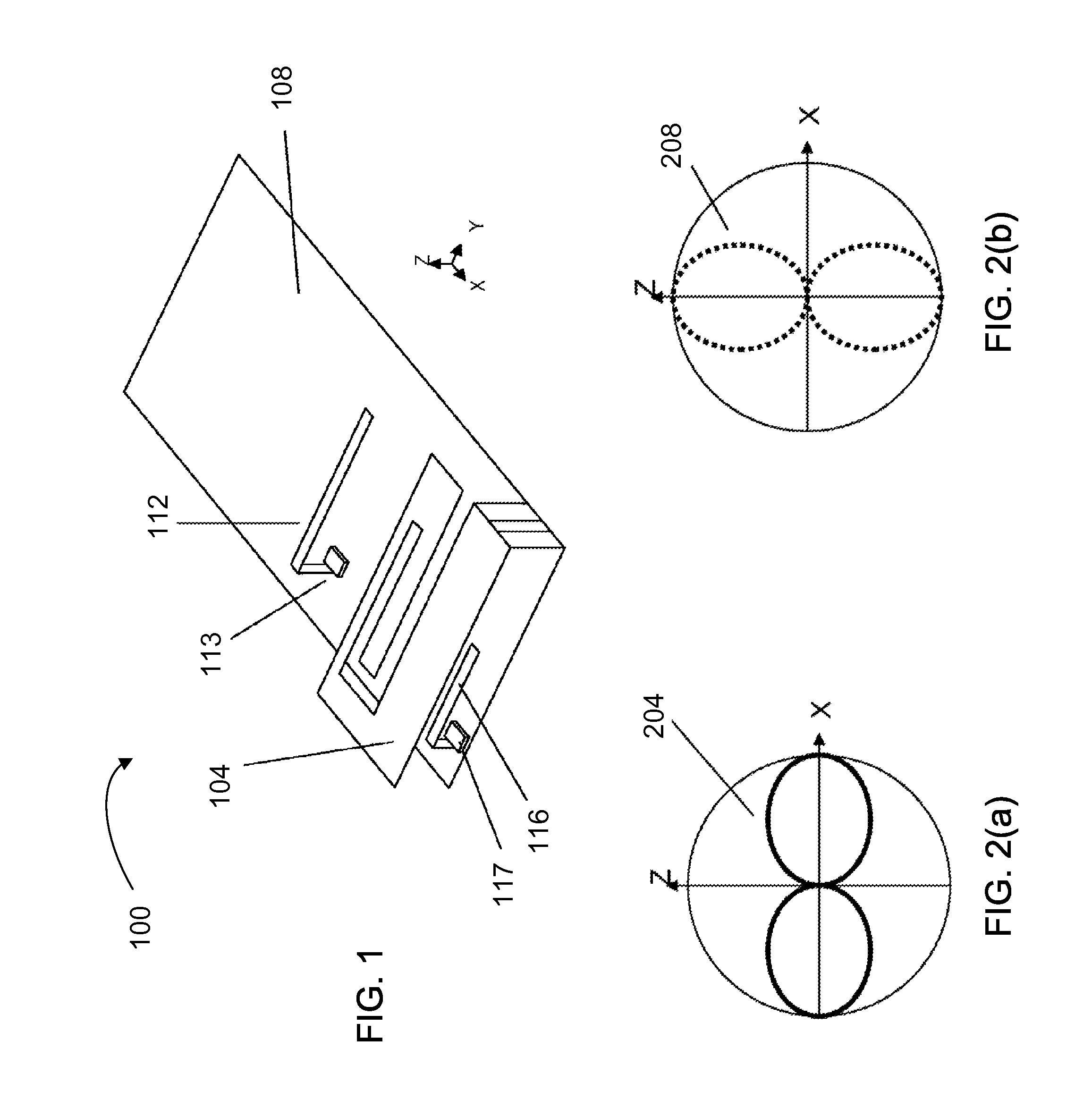
[0023]Active antennas which could replace the role of several passive antennas in pattern or polarization diversity schemes can be used to reduce the number of antennas. For example, a modal antenna, also referred to as a null-steering antenna, can generate multiple modes corresponding to multiple radiation patterns, equivalent to having a set of antennas with the same feed. By using the modal antenna capable of generating different radiation patterns, it is possible to exploit a priori knowledge of antenna nulls and lobes in the different modes for steering the beam to have nulls in dominant interference directions while keeping gain in desired directions. Accordingly, implementation of a modal antenna may allow for pattern and / or polarization diversity with one antenna, thereby requiring less volume and area than using multiple antennas for diversity. Examples of structures and implementations of the modal antennas are provided in U.S. Pat. No. 7,911,402, entitled “ANTENNA AND MET...


PUM


Abstract

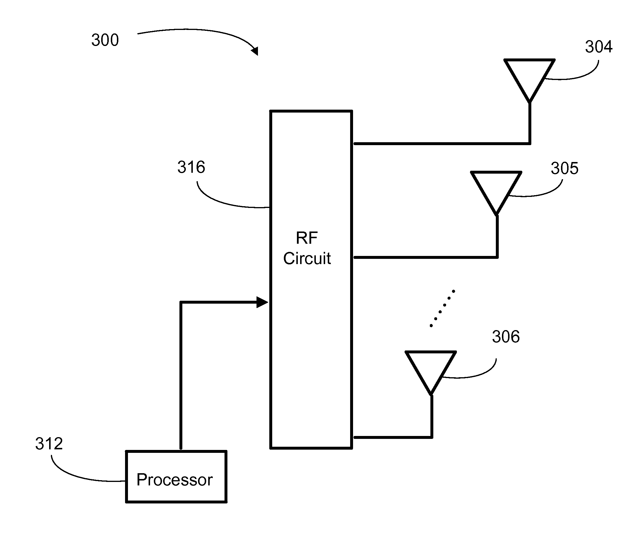
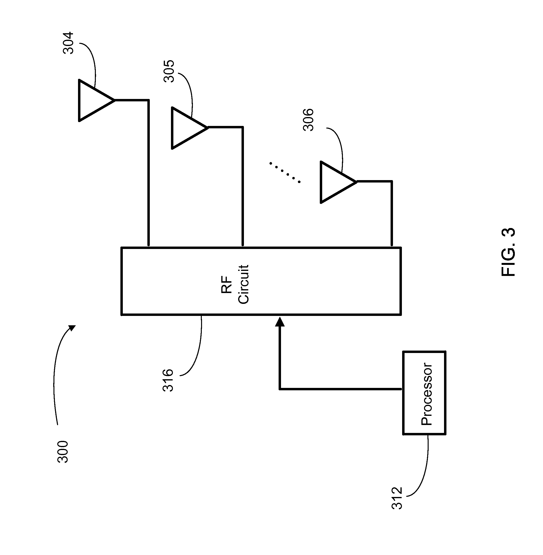
A system and method for optimizing the performance for MIMO are provided, the system including multiple antennas, including at least one modal antenna, wherein each of the at least one modal antenna has multiple modes corresponding to multiple radiation patterns, and a processor coupled to the multiple antennas and configured to select a mode among the multiple modes to optimize signal quality for each time interval based on a CQI by considering envelop correlation effects.

Description

CROSS-REFERENCE TO RELATED APPLICATIONS[0001]This application is a continuation in part of U.S. Ser. No. 13 / 749,627, filed Jan. 24, 2013, and titled “MODAL COGNITIVE DIVERSITY FOR MOBILE COMMUNICATION MIMO SYSTEMS”; and[0002]claims benefit of priority with U.S. Ser. No. 61 / 725,019, filed Nov. 11, 2012, and titled “STATE PREDICTION PROCESS AND METHODOLOGY”;[0003]the contents of each of which are hereby incorporated by reference.BACKGROUND OF THE INVENTION[0004]As new generations of handsets and other wireless communication devices become smaller and embedded with increased applications, new antenna designs, system configurations and controlling algorithms are required to enable new capabilities and to improve QOS.[0005]In many instances, the line of sight between a transmitter and a receiver involved in the communication becomes blocked or shadowed with obstacles such as walls and other objects. Each signal bounce may introduce phase shifts, time delays, attenuations and distortions,...

Claims


Application Information

Patent Timeline
Patent Type & Authority Patents(United States)
IPC IPC(8): H04B15/00H01Q1/24H01Q3/44H01Q19/28H04B7/06H04B7/04H04B7/10
CPCH01Q1/243H01Q3/44H01Q19/28H04B7/0689H04B7/10H04B7/0413H04B17/318H04L5/0057
Inventor PAJONA, OLIVIERROWSON, SEBASTIANDESCLOS, LAURENT
Owner KYOCERA AVX COMPONENTS (SAN DIEGO) INC
Learn More