
Swivelling assembly for a vehicle seat

a vehicle seat and assembly technology, applied in the field of vehicle seats, can solve the problems of increasing inventory and manufacturing costs, many constraints to satisfy,

Inactive Publication Date: 2016-08-16
AUGER LAURENT
View PDF38 Cites 14 Cited by
  • Summary
  • Abstract
  • Description
  • Claims
  • Application Information

AI Technical Summary

Benefits of technology

The patent text is about a new feature for vehicles that allows the seat to move forward and backward to make it easier for people to get in and out of the vehicle. This is especially useful when the original seat is power-operated.

Problems solved by technology

While many prior art mechanisms can generally fulfill the main objective of operating a vehicle seat between a forward facing position and a door facing position, they also generally entail one or more of the following disadvantages.
The vehicle seat mechanisms of the prior art are generally represented by relatively expensive assemblies of custom made components, which renders the mechanisms particularly onerous to manufacture, as well as to buy for users having typically low incomes typical of persons with reduced mobility or elderly people.
In addition, there are many constraints to satisfy when retrofitting a swiveling vehicle seat mechanism to a car or other vehicle.
To provide swiveling seat mechanisms for a large range of vehicles, there is a need to store many different swiveling seat mechanisms, which increases inventory and manufacturing cost.

Method used


Image

  • Swivelling assembly for a vehicle seat
  • Swivelling assembly for a vehicle seat
  • Swivelling assembly for a vehicle seat

Examples


first embodiment

[0093]Now referring to FIGS. 8A and 8B, there is illustrated an alternate embodiment of a swiveling assembly 100 according to the present invention. In the presently described embodiment, the swiveling assembly 100 is substantially similar to the swiveling assembly 10 described above, with the exception that it further includes an anchor 102. The anchor 102 is for better securing the seat support 40 to the vehicle floor 14 than can be solely provided by the swivel 16.

[0094]Typically, a plurality of anchors 102 is provided for example four (4) anchors 102 disposed in a radially equidistantly spaced apart relationship, with each anchor 102 being for example positioned substantially vertically in register with the original anchoring position of the vehicle seat 12 with the vehicle floor 14.

[0095]Referring to FIGS. 7A and 7B, each anchor 102 includes a first anchor element 104 mountable so as to be fixed relative to the vehicle floor 14. To that effect, the first anchor element 104 may ...

second embodiment

[0102]Now referring to FIG. 9, there is illustrated yet another alternate embodiment of a swiveling assembly 200 according to the present invention. In the presently described embodiment, the swiveling assembly 200 is substantially similar to the first or second embodiment of a swiveling assembly 10 or 100 respectively, as described above, with the exception that it further includes a pair of telescopic rails 202 (only one of which is seen in the drawings) that are substantially parallel to each other and mounted to the seat support 40. The telescopic rails 202 may be installed on a conventional or static vehicle seat (e.g. a vehicle seat that is not power operated), or a powered vehicle seat already provided with a forward and backward adjustment mechanism.

[0103]The pair of telescopic rails 202 is usable for providing a forward and backward position adjustment mechanism of the vehicle seat 12 having requiring a relatively longer range than the factory installed mechanism. The teles...

third embodiment

[0105]Now referring to FIG. 10, there is illustrated another alternate embodiment of a swiveling assembly 300 according to the present invention. In the presently described embodiment, the swiveling assembly 300 is substantially similar to the first, second and third embodiment of a swiveling assembly 10, 100 or 200 respectively, as described above, with the exception that it further includes a reinforcing plate 302. The reinforcing plate 302 is adapted to be mounted between the original seat anchoring threaded bores 114 typically embedded in structural frame members under the vehicle floor 14, and the other components of one of the embodiments described above. Thus, the reinforcing plate 302 provides a relatively stronger and stable base on which to attach the swivel 16 and, selectively, the anchors 102, compared to the typically thin sheet of metal that is generally found centrally under the vehicle seat 12.

[0106]The reinforcing plate 302 may be substantially square or rectangular...


PUM


Abstract

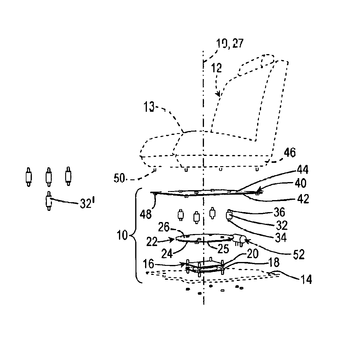
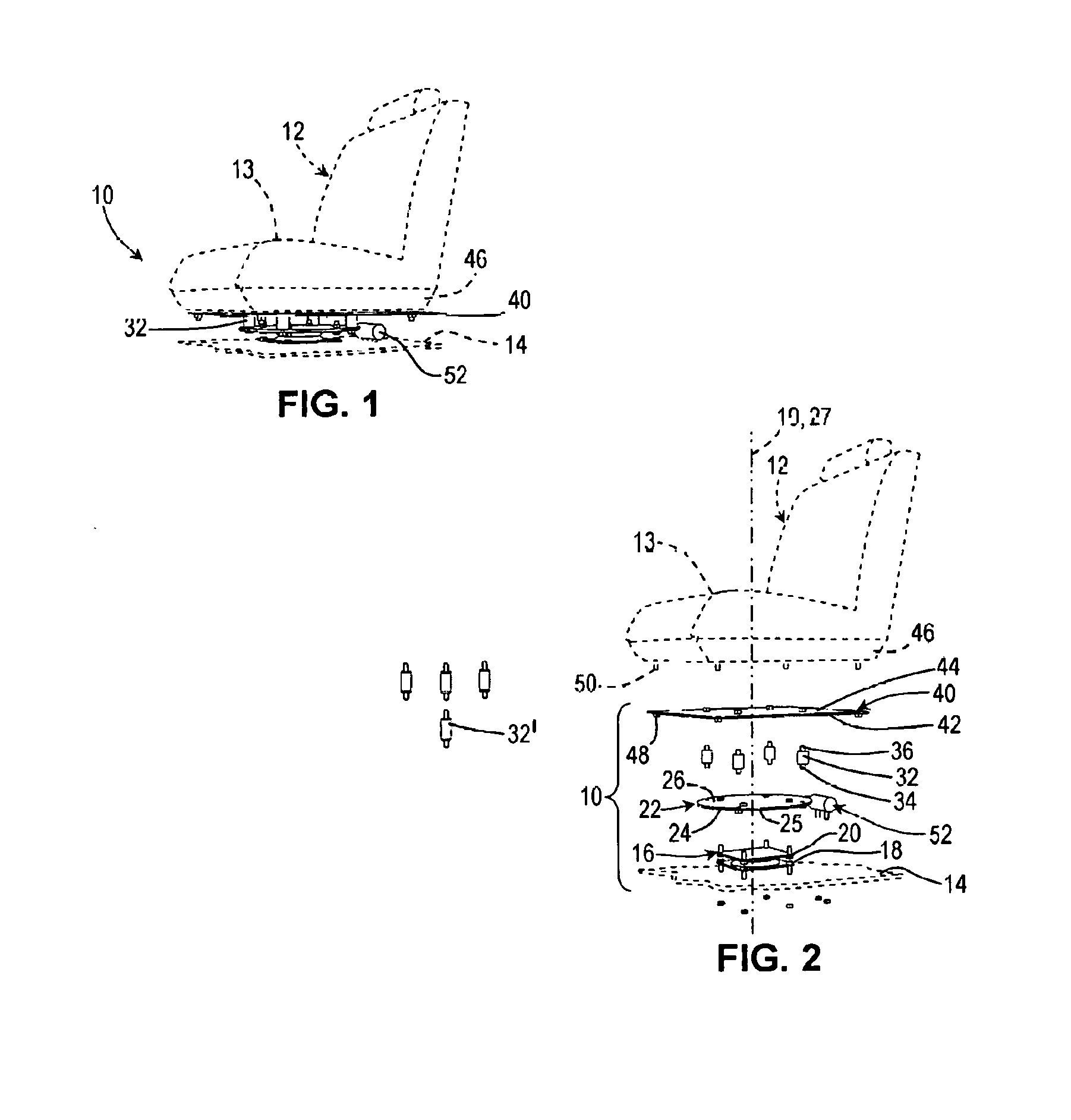
A swiveling assembly comprising a swivel, the swivel comprising a swivel bottom element and a swivel top element rotatable relative thereto; a gear provided with gear teeth along at least a portion thereof, the gear being mounted to the swivel top element; an actuator operatively coupled to the gear teeth for selectively rotating the gear relative to the swivel bottom element; at least one spacer element mounted to the gear and extending away therefrom; and a seat support mounted to the at least one spacer element so as to be spaced apart from the gear, a vehicle seat being mountable to the seat support. The at least one spacer element raises the seat support so that the vehicle seat is above a doorstep when the swiveling assembly is operatively mounted to a vehicle floor and the vehicle seat is operatively mounted to the swiveling assembly.

Description

FIELD OF THE INVENTION[0001]The present invention relates generally to vehicle seats and, more particularly, to a swiveling assembly for a vehicle seat, such as a front car seat, to be swiveled about a generally vertical axis while also allowing conventional linear horizontal slidable movements of the vehicle seat within the vehicle if desired.BACKGROUND[0002]Adjustable vehicle seat mechanisms are well known in the car industry for providing means to adjust the position and / or ergonomic configuration of the seat the car driver or passenger is sitting in.[0003]The present invention is more particularly concerned with powered vehicle seat mechanisms having adjustment characteristics that are not typically found in factory installed powered seat mechanisms. These powered seat mechanisms of the prior art generally provide a vehicle seat that can be swiveled about a vertical axis, as well as slid linearly horizontally towards the adjacent door bay of the vehicle. Such vehicle seat mechan...

Claims


Application Information

Patent Timeline
Patent Type & Authority Patents(United States)
IPC IPC(8): A47C1/00B60N2/24B60N2/06B60N2/14B60N2/02
CPCB60N2/062B60N2/14B60N2/245B60N2/0232B60N2/06B60N2/02246
Inventor AUGER, LAURENT
Owner AUGER LAURENT
Learn More