
System and method for transferring electric energy to a vehicle using constant current operation of segments of a conductor arrangement

a technology of electric energy and conductor arrangement, which is applied in the direction of charging stations, transportation and packaging, rail devices, etc., can solve the problems of reducing the cost of manufacturing such a system and not allowing individual operation of the segments, and achieves the effect of reducing the effort for manufacturing and installing the system and high efficiency of operating the segments

Active Publication Date: 2016-07-19
BOMBARDIER TRANSPORTATION GMBH
View PDF31 Cites 0 Cited by
  • Summary
  • Abstract
  • Description
  • Claims
  • Application Information

AI Technical Summary

Benefits of technology

This approach enhances the efficiency of energy transfer, reduces manufacturing and installation costs, and allows for flexible operation of segments, optimizing power delivery to vehicles while minimizing reactive power production.

Problems solved by technology

However, this does not allow for individual operation of the segments, if the segments are connected in parallel to each other with the current supply.
In addition, these components produce a significant part of the costs of manufacturing such a system.

Method used


Image

  • System and method for transferring electric energy to a vehicle using constant current operation of segments of a conductor arrangement
  • System and method for transferring electric energy to a vehicle using constant current operation of segments of a conductor arrangement
  • System and method for transferring electric energy to a vehicle using constant current operation of segments of a conductor arrangement

Examples


Embodiment Construction

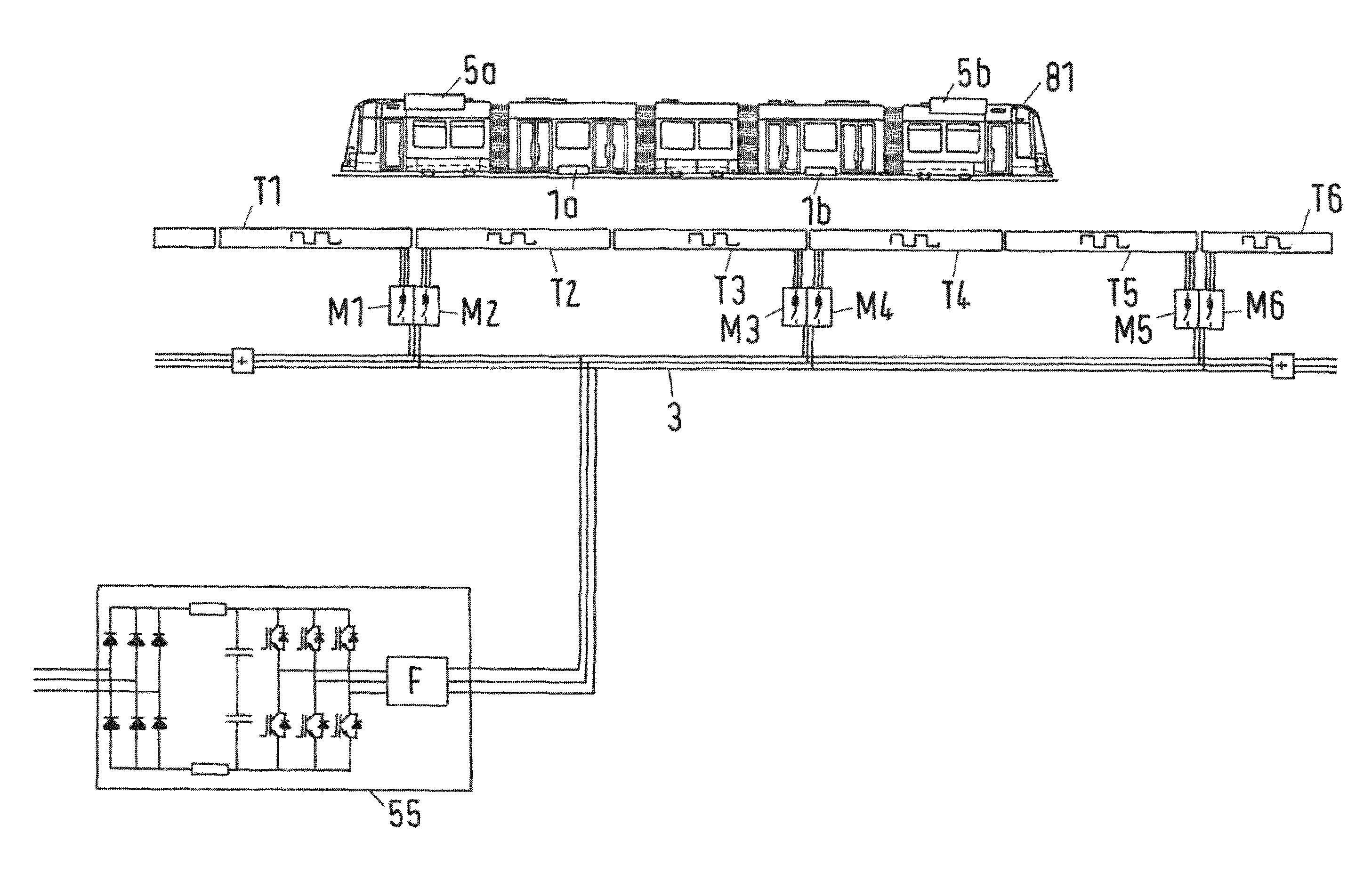
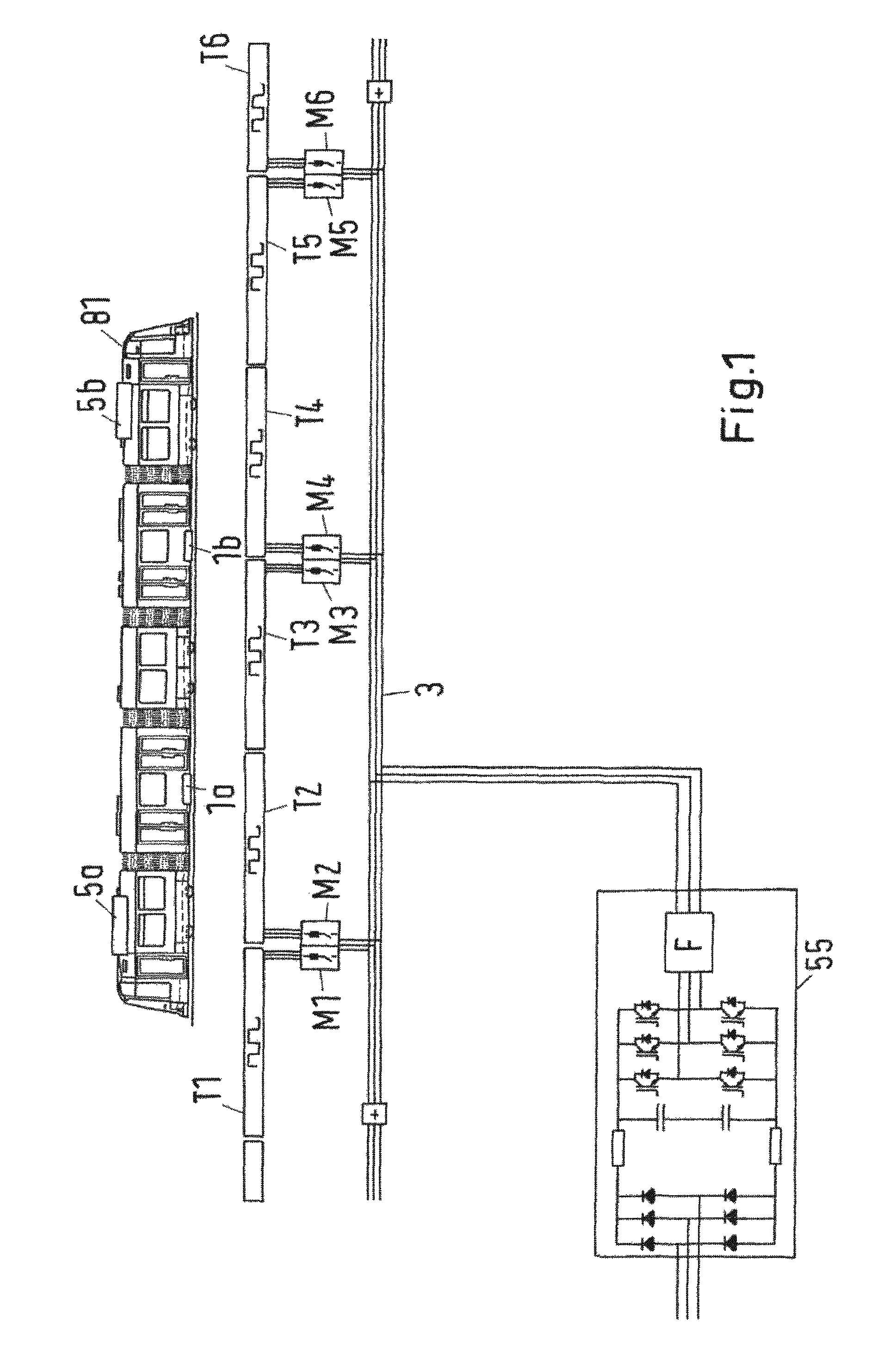
[0075]FIG. 1 schematically shows a vehicle 81, in particular a light rail vehicle such as a tram, travelling along a track. In this specific embodiment, the vehicle 81 comprises two receivers 1a, 1b for receiving electromagnetic fields which are produced by segments T1, . . . , T6 of the track. The receivers 1a, 1b are located at the bottom of the vehicle 81, in a middle section of the front part and back part of the vehicle 81. The receivers may comprise a plurality of lines for producing different phases of an alternating current. A vehicle may have any other number of receivers.

[0076]The receivers 1a, 1b are connected with other equipment within the vehicle 81, such as with a converter (not shown) for converting an alternating current produced by the receivers 1 to a direct current. For example, the direct current can be used to charge batteries or other energy storages 5a, 5b of the vehicle 81. Furthermore, the direct current can be inverted into an alternating current used to f...


PUM

PropertyMeasurementUnit
currentaaaaaaaaaa
voltageaaaaaaaaaa
electric energyaaaaaaaaaa

Abstract

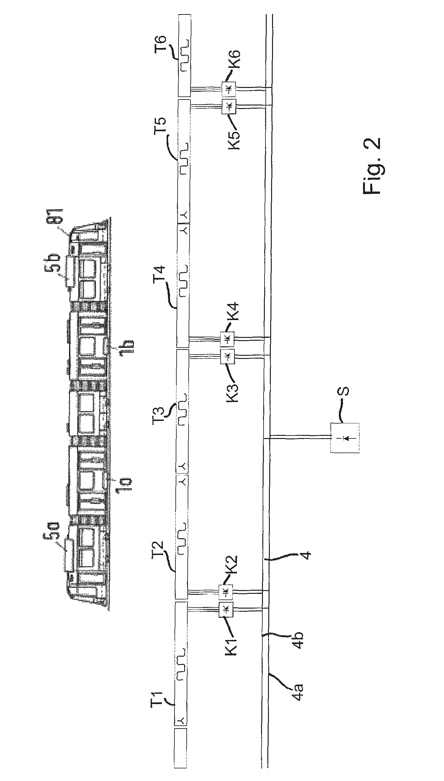
A system for transferring electric energy to a vehicle such as a track bound vehicle or road automobile. The system includes an electric conductor arrangement which produces an alternating electromagnetic field, transfers electromagnetic energy to the vehicle and includes a plurality of segments. Each segment extends along the vehicle path of travel and includes one line for each phase of alternating current carried by the segment. The system includes a current supply for conducting electric energy to the segments which are electrically connected in parallel. At least one segment is coupled to the current supply via a constant current source. Each constant current source includes one or more inductances and one or more capacitances, the inductances and capacitances being adapted to each other and the input side of the constant current source so that a constant current is output to the output side.

Description

CROSS-REFERENCE TO RELATED APPLICATIONS[0001]This application is the United States national phase of International Application No. PCT / EP2012 / 061027 filed Jun. 11, 2012, and claims priority to United Kingdom Patent Application No. 1109825.8 filed Jun. 10, 2011, the disclosures of which are hereby incorporated in their entirety by reference.BACKGROUND OF THE INVENTION[0002]1. Field of the Invention[0003]The invention relates to the transfer of electric energy to a vehicle, in particular to a track bound vehicle such as a light rail vehicle (e.g. a tram) or to a road automobile such as a bus. A corresponding system comprises an electric conductor arrangement for producing an alternating electromagnetic field and for thereby transferring electromagnetic energy to the vehicle. The conductor arrangement comprises a plurality of segments, wherein each segment extends along a different section of the path of travel of the vehicle. At least one of the segments is coupled to a current supply...

Claims


Application Information

Patent Timeline
Patent Type & Authority Patents(United States)
IPC IPC(8): B60L5/00B60M3/04B60L9/00
CPCH02J50/20B60L5/005B60L9/00B60M3/04B60L2200/18B60L2200/26Y10T29/49117H02J50/12H02J50/40H02J50/90Y02T10/70Y02T10/7072Y02T90/14B60Y2200/91B60Y2200/92B60L53/12B60M7/003B60L2200/30B60Y2200/30H02J5/005
Inventor VOLLENWYDER, KURTWORONOWICZ, KONRADCZAINSKI, ROBERTMEINS, JURGEN
Owner BOMBARDIER TRANSPORTATION GMBH
Learn More