
Rotary-wing drone comprising autonomous means for determining a position in an absolute coordinate system linked to the ground

a technology of absolute coordinate system and drone, which is applied in the direction of vehicle position/course/altitude control, process and machine control, instruments, etc., can solve the problems of inability to operate in an autonomous navigation system, based on the reception of signals emitted by several satellites, and in a closed environment. achieve the effect of not involving the user in any way, and without risk of disturban

Inactive Publication Date: 2016-07-12
PARROT
View PDF2 Cites 44 Cited by
  • Summary
  • Abstract
  • Description
  • Claims
  • Application Information

AI Technical Summary

Benefits of technology

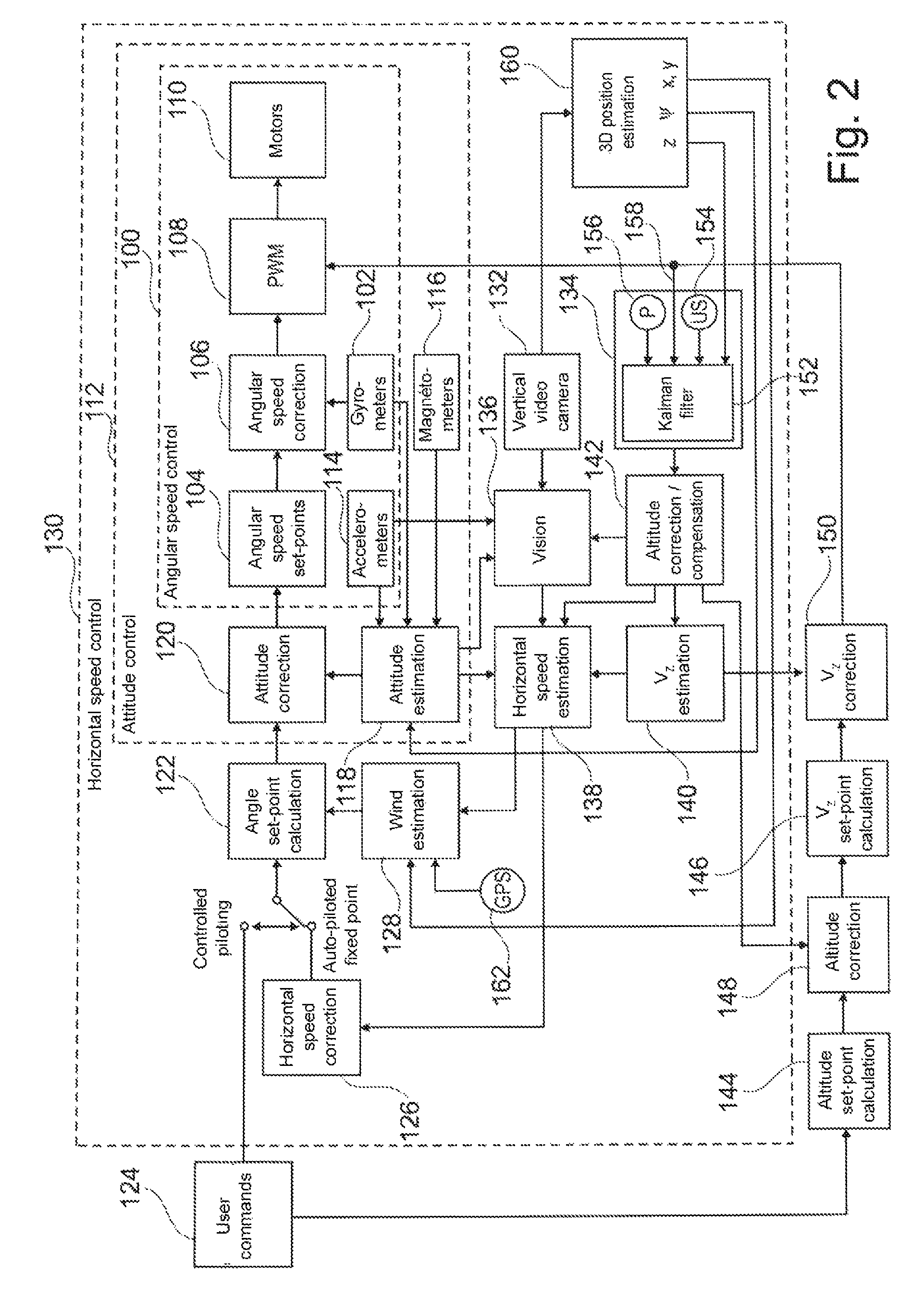
The invention is a drone with multiple rotors driven by separate motors, which can be controlled to pilot the drone in altitude and speed. The drone has sensors to detect its state, including a camera to capture images, magnetometers, accelerometers, and an altimeter to measure its altitude. The drone also has a navigation system that uses image analysis to determine its position relative to the ground. The invention includes a predictive filter to estimate the drone's state based on the motor commands and the sensor signals. The drone can also have a carpet with unique patterns that can be identified by the drone's visual characteristics, such as color and pattern design. The technical effects of this invention include improved control and navigation for drones, as well as improved safety and reliability for autonomous drones.

Problems solved by technology

The GPS technique, based on the reception of signals emitted by several satellites, are however inoperative in a closed environment, inside a building, due to the impossibility to suitably pick up these signals.
Hence, it is not an autonomous navigation system.

Method used


Image

  • Rotary-wing drone comprising autonomous means for determining a position in an absolute coordinate system linked to the ground
  • Rotary-wing drone comprising autonomous means for determining a position in an absolute coordinate system linked to the ground
  • Rotary-wing drone comprising autonomous means for determining a position in an absolute coordinate system linked to the ground

Examples


Embodiment Construction

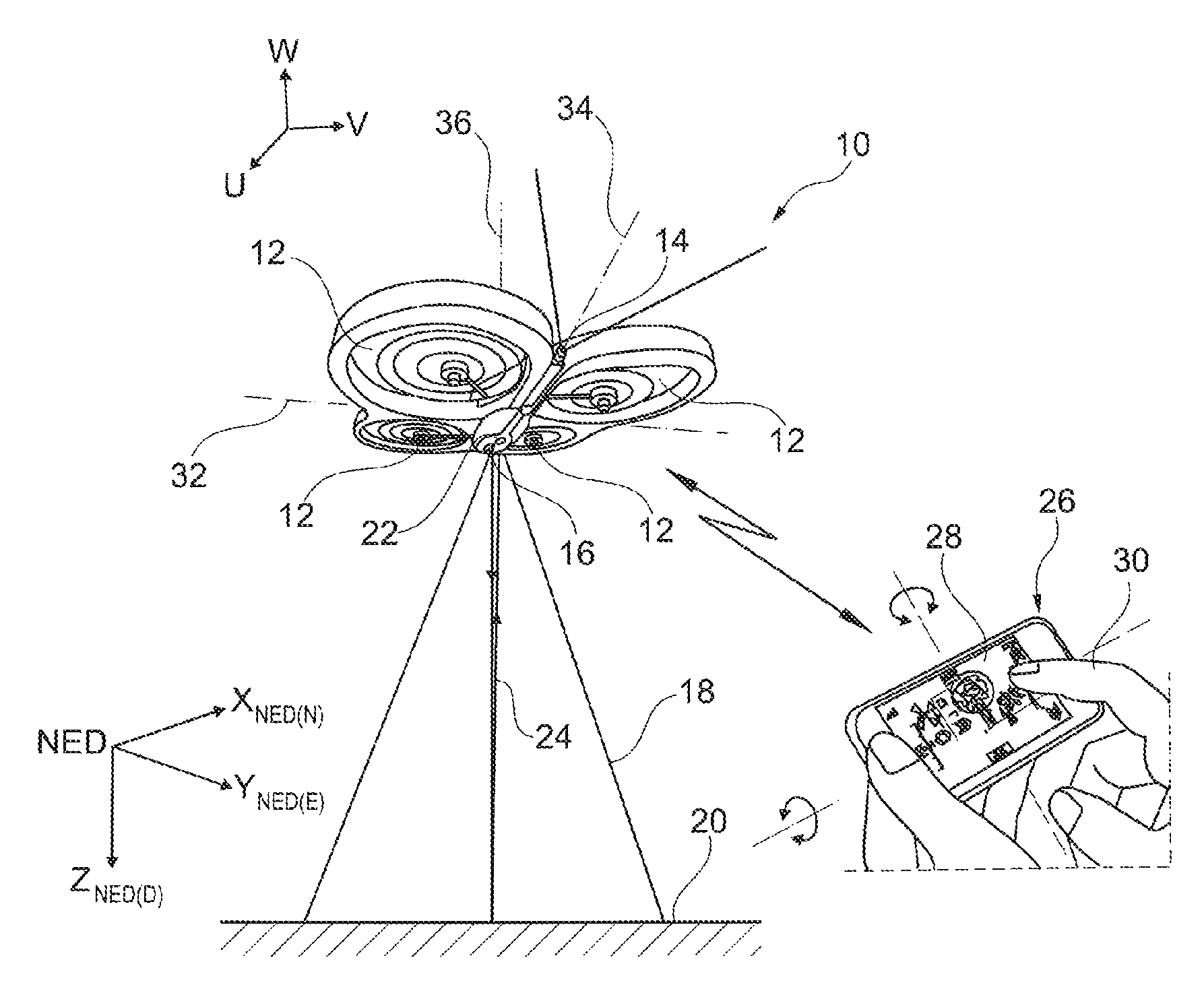
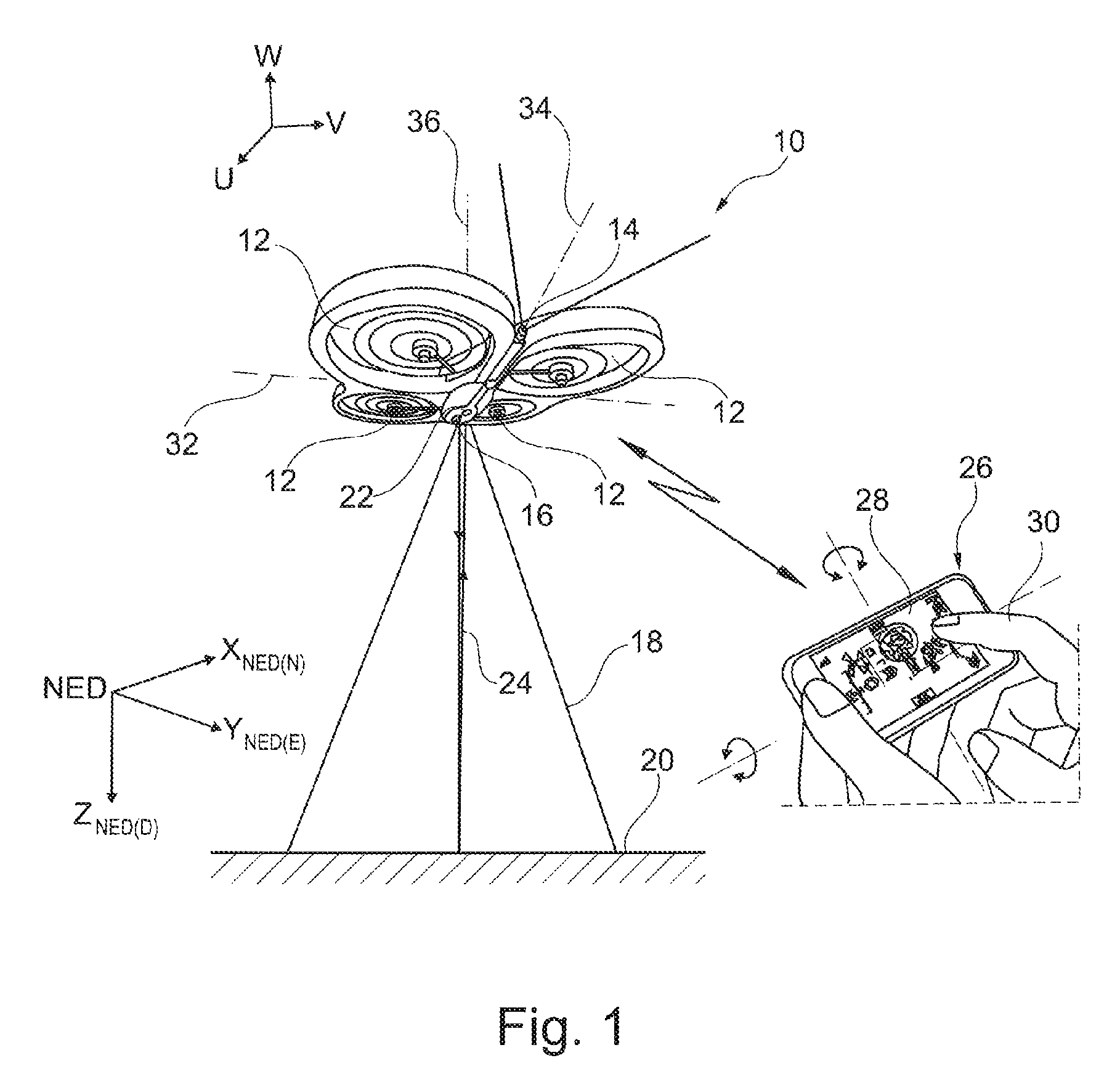
[0039]In FIG. 1, the reference 10 generally denotes a drone, for example a quadricopter such as the above-mentioned AR.Drone described in the WO 2010 / 061099 A2 and EP 2 364 757 A1, as well as the FR 2 915 569 A1 (which describes in particular the system of gyrometers and accelerometers used by the drone), EP 2 431 084 A1 et EP 2 497 555 A1 (which describe in particular how to control predetermined trajectories).

[0040]The drone 10 includes four coplanar rotors 12, whose motors are controlled independently by an integrated navigation and attitude control system. A first front-view camera 14 is provided, which allows to obtain an image of the scene toward which is oriented the drone, for example a CMOS-sensor wide-angle camera. The drone also includes a second, vertical-view camera 16, pointing downward (beam 18), adapted to pick up successive images of the overflown ground 20 and used in particular to evaluate the speed of the drone relative to the ground.

[0041]Inertial sensors (accel...


PUM


Abstract

The drone comprises: a vertical-view camera (132) pointing downward to pick up images of a scene of the ground overflown by the drone; gyrometer, magnetometer and accelerometer sensors (176); and an altimeter (174). Navigation means determine position coordinates (X, Y, Z) of the drone in an absolute coordinate system linked to the ground. These means are autonomous, operating without reception of external signals. They include image analysis means, adapted to derive a position signal from an analysis of known predetermined patterns (210), present in the scene picked up by the camera, and they implement a predictive-filter estimator (172) incorporating a representation of a dynamic model of the drone, with as an input the position signal, a horizontal speed signal, linear and rotational acceleration signals, and an altitude signal.

Description

BACKGROUND OF THE INVENTION[0001]The invention relates to rotary-wing drones such as quadricopters or the like.[0002]Such drones are provided with multiple rotors driven by respective motors that can be controlled in a differentiated manner so as to pilot the drone in attitude and speed.[0003]A typical example of such a drone is the AR.Drone of Parrot SA, Paris, France, which is a quadricopter equipped with a series of sensors (accelerometers, three-axis gyrometer, altimeter), a front camera picking up an image of the scene toward which the drone is directed, and a vertical-view camera picking up an image of the overflown ground.[0004]The documents WO 2010 / 061099 A2, EP 2 364 757 A1, EP 2 431 084 A1 and EP 2 497 555 A1 (Parrot SA) describe such a drone, as well as the principle of piloting the latter through a phone or a multimedia player having a touch screen and integrated accelerometers, for example a cellular phone of the iPhone type or a player or a multimedia tablet of the iPo...

Claims


Application Information

Patent Timeline
Patent Type & Authority Patents(United States)
IPC IPC(8): B64C39/02G05D1/10
CPCB64C39/024G05D1/102B64C2201/024B64C2201/141B64U10/14B64U2201/10B64U2201/20
Inventor RISCHMULLER, MICHAELCHEVALLEY, LAURECALLOU, FRANCOISCALDICHOURY, ETIENNE
Owner PARROT
Learn More