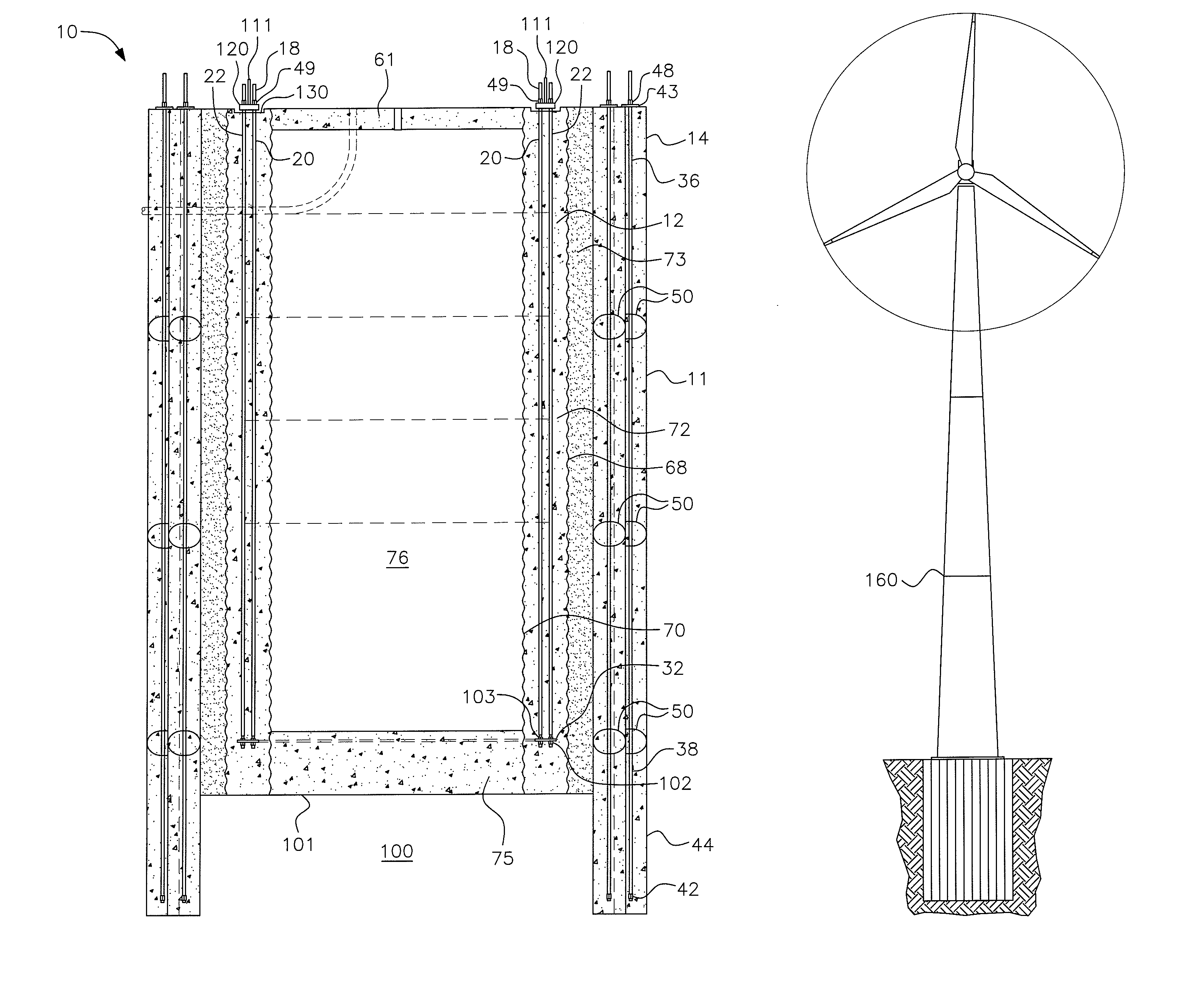
Perimeter pile anchor foundation
a technology of anchoring foundations and perimeter piles, which is applied in the direction of foundation engineering, bulkheads/piles, construction, etc., can solve the problems of limited foundations
- Summary
- Abstract
- Description
- Claims
- Application Information
AI Technical Summary
Benefits of technology
Problems solved by technology
Method used
Image
Examples
first embodiment
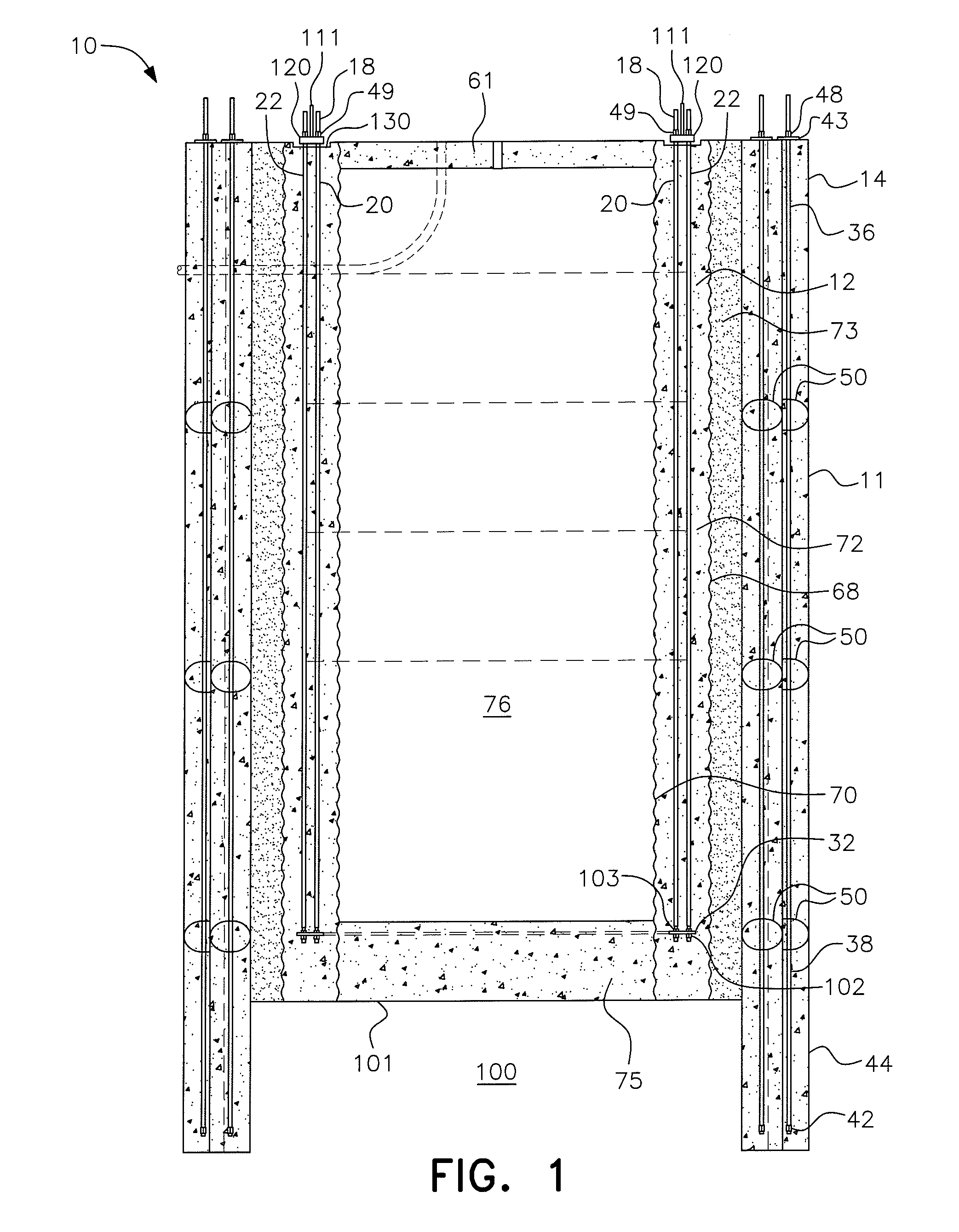
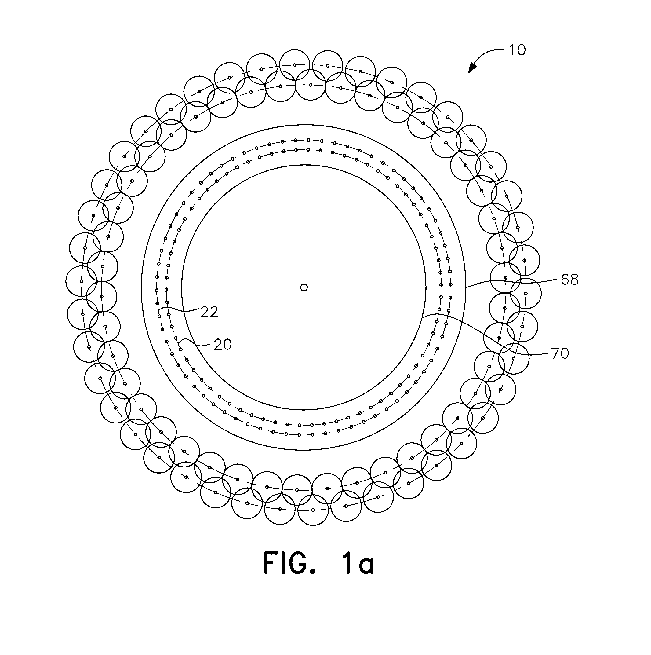
[0044]a perimeter pile anchor foundation in accordance with the present invention is shown in FIGS. 1, 1a and 2. The perimeter pile anchor foundation, generally designated by reference numeral 10, has a plurality of pile anchors or “piles”, each generally designated by the reference numeral 14 extending vertically downward into the soil 100 and forming a perimeter wall, generally designated by reference numeral 11, for the foundation 10. The pile anchors 14 thus serve to secure the concrete foundation 10 into the ground. A first or outer CMP 68 is placed vertically in the excavation inside the perimeter wall 11 to form an outer annular ring, generally designated by reference numeral 73, between the inside of the perimeter wall 11 and the outer CMP 68.
[0045]According to the first embodiment, a second or inner CMP 70 is placed inside the outer CMP 68, forming an inner annular ring, also referred to herein as the foundation ring 72. Extending through the concrete foundation ring 72 is ...
second embodiment
[0067] shown in FIG. 10, after the pile anchors are formed, only an inner CMP 70 is vertically placed inside the pile perimeter and spaced therefrom to create an annular foundation ring 80 between the CMP 70 and the piles 14. A direct embedded section, generally designated by reference numeral 85, is placed near the top of the foundation ring 80. The direct embedded section 85 includes a generally U-shaped reinforcing steel cage, generally designated by reference numeral 87, formed by a loop of rebar coupled with a structure extension, generally designated by reference numeral 116, which is shown in FIG. 11. The cage 87 is constituted by a piece of rebar bent to have a generally vertical inner leg 88 and a generally vertical outer leg 89 joined at the top by a generally horizontal length 90 of the rebar extending through holes 110 in the generally cylindrical side wall 112 of the extension 116 of the embedded section 85 to form the generally U-shaped configuration for cage 87. Rebar...
PUM
 Abstract
Description
Claims
Application Information
 - R&D
- Intellectual Property
- Life Sciences
- Materials
- Tech Scout
- Unparalleled Data Quality
- Higher Quality Content
- 60% Fewer Hallucinations
Browse by: Latest US Patents, China's latest patents, Technical Efficacy Thesaurus, Application Domain, Technology Topic, Popular Technical Reports.
© 2025 PatSnap. All rights reserved.Legal|Privacy policy|Modern Slavery Act Transparency Statement|Sitemap|About US| Contact US: help@patsnap.com


