Current measurement
a current measurement and current technology, applied in the direction of instruments, electric devices, base element modifications, etc., can solve the problems of inaccuracy in determination of load drawn current signal, transfer function of measurement arrangement is liable to be unknown, etc., to achieve accurate power measurement, accurate power measurement, and accurate current measurement.
- Summary
- Abstract
- Description
- Claims
- Application Information
AI Technical Summary
Benefits of technology
Problems solved by technology
Method used
Image
Examples
first embodiment
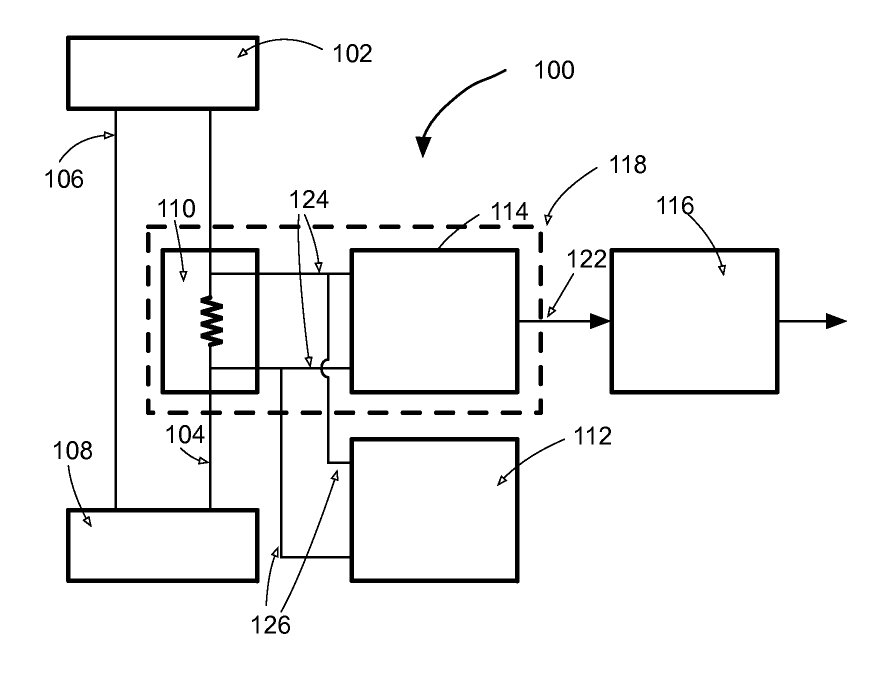
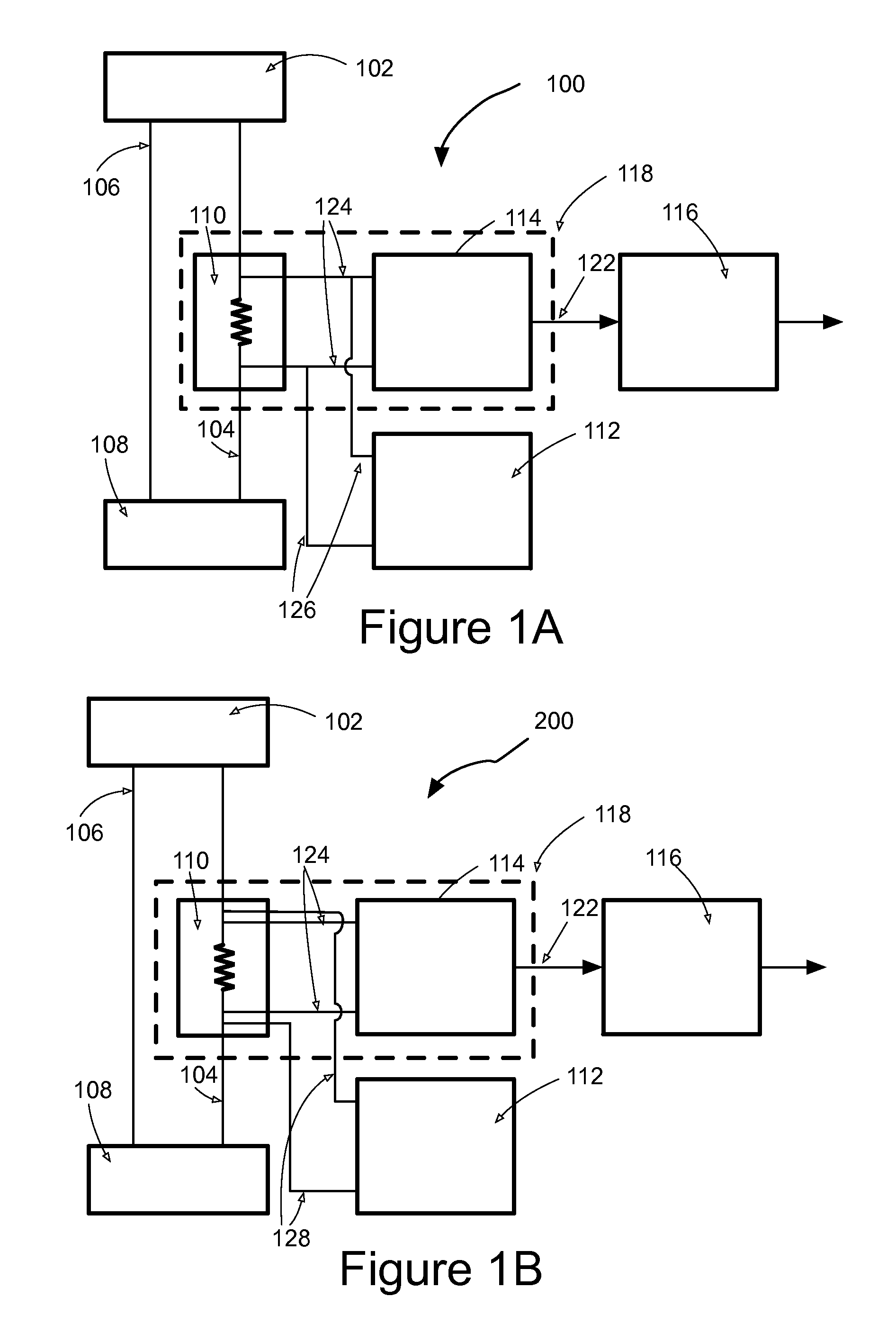
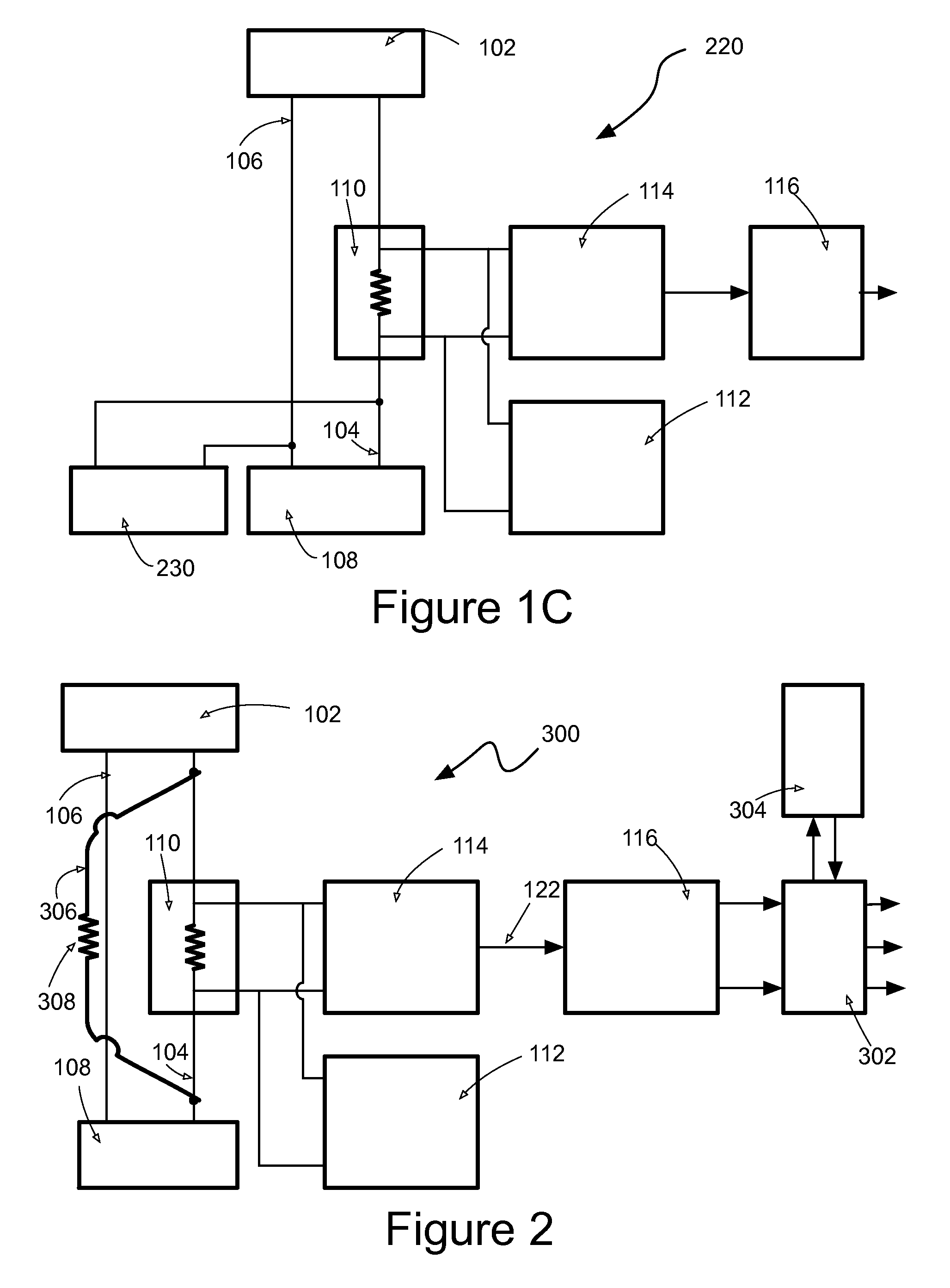
[0108]current measurement apparatus 100 having a first form of electrical connection to a shunt resistor is shown in FIG. 1A. The current measurement apparatus 100 forms part of an electricity consumption meter (not shown) installed at a point of supply to residential or business premises. A single phase mains alternating current electricity source 102 with live 104 and neutral 106 supply wires are shown in FIG. 1A. Energy consuming apparatus at the residential or business premises is represented by a load 108. The current measurement apparatus 100 comprises a shunt resistor 110 (which constitutes a current sensor) in the live supply wire 104 in series with the load 108 between the load and the electricity supply 102. The shunt resistor 110 presents a low value of resistance, such as a resistance of 1 mΩ. The shunt resistor 110 is formed from a length of electrical wire, a length of conductive track on a printed circuit board, a discrete component, a conductor comprised in an integr...
second embodiment
[0112]current measurement apparatus 200 having a second form of electrical connection to the shunt resistor is shown in FIG. 1B. Features in common with the current measurement apparatus 100 of FIG. 1A are indicated by the same reference numerals and the reader's attention is directed to the description provided above with reference to FIG. 1A for a description of the form and function of such common features. A first pair of wires 124 from the voltage measuring apparatus 114 is as per FIG. 1A. A second pair of wires 128 from the signal source 112 establishes an electrical connection by direct connection to opposing ends of the shunt resistor 110 whereby the first and second pairs of wires constitute separate conduction paths between the shunt resistor 110 and each of the voltage measuring apparatus 114 and the signal source 112. The arrangement of FIG. 1B is appropriate where the conduction path between the resistor shunt 110 and the voltage measuring apparatus 114 has parasitic im...
fourth embodiment
[0117]Current measurement apparatus 400 which is configured to measure current in each of a live and neutral wire of an electricity supply is shown in FIG. 3A. The current measurement apparatus 400 comprises a first shunt resistor 402 in the live wire 404 between an ac power source 406 and a load 408 and a second shunt resistor 410 in the neutral wire 412 between the ac power source 406 and the load 408. The current measurement apparatus 400 further comprises a first unit 414 and second unit 416. The first unit 414 comprises a first signal source 418, first voltage measuring apparatus 420 and first signal processing circuitry 422. The second unit 416 comprises a second signal source, second voltage measuring apparatus and second signal processing circuitry. The signal source 418, voltage measuring apparatus 420 and signal processing circuitry 422 of each of the first and second units 414, 416 are configured and operative to determine the load drawn current signals drawn through a r...
PUM
 Abstract
Description
Claims
Application Information
 - R&D
- Intellectual Property
- Life Sciences
- Materials
- Tech Scout
- Unparalleled Data Quality
- Higher Quality Content
- 60% Fewer Hallucinations
Browse by: Latest US Patents, China's latest patents, Technical Efficacy Thesaurus, Application Domain, Technology Topic, Popular Technical Reports.
© 2025 PatSnap. All rights reserved.Legal|Privacy policy|Modern Slavery Act Transparency Statement|Sitemap|About US| Contact US: help@patsnap.com


