Eureka AIR delivers breakthrough ideas for toughest innovation challenges, trusted by R&D personnel around the world.

Systems, components, and methods for electronic candles with moving flames

a technology of electronic candles and moving flames, applied in the field of electric simulated candles, can solve the problems of not creating the illusion of a real flickering flame and not being satisfactory to people, and achieve the effects of convenient and economical production, high efficiency of operation, and strong construction

Active Publication Date: 2016-04-26
WM B COLEMAN
View PDF8 Cites 13 Cited by
  • Summary
  • Abstract
  • Description
  • Claims
  • Application Information

AI Technical Summary

Benefits of technology

[0013]Other objects are to provide an improved device of the character described above, that is easily and economically produced, which is sturdy in construction and which is highly effective in operation.

Problems solved by technology

Unfortunately, wax candles use a burning wicker for illumination, and the open flame requires precaution and attention to prevent harm caused by fire.
However, such heated elements do not create an illusion of a real flickering flame and may not be satisfactory for people who seek the appeal of real wax candles.

Method used


Image

  • Systems, components, and methods for electronic candles with moving flames
  • Systems, components, and methods for electronic candles with moving flames
  • Systems, components, and methods for electronic candles with moving flames

Examples


Embodiment Construction

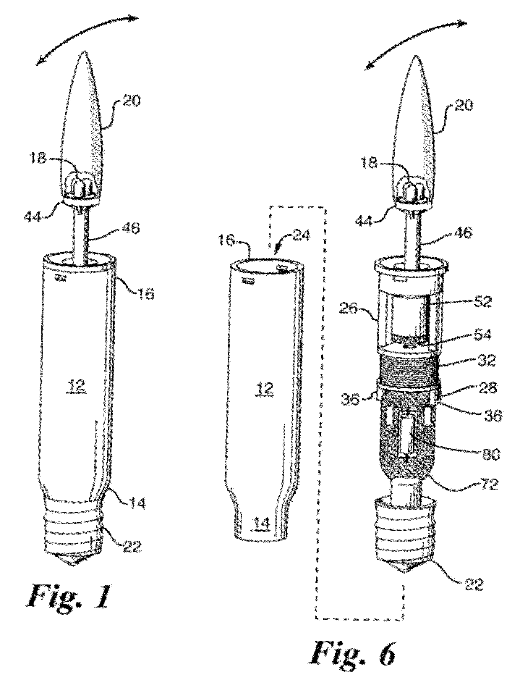
[0024]Referring to FIGS. 1-6, an electronic candle, indicated generally by numeral 10, includes an elongated candle-like shell 12, a light-emitting element 18 disposed proximate the tip of the shell 12 and a frosted, translucent cap member 20 having the contour of a flame of a burning candle. The cap member 20 covers the light-emitting element 18. In the preferred embodiment, the light-emitting element 18 is a light-emitting diode. The shell 12 has a top end 16 and a bottom end 14. A screw base assembly 22 is disposed on the bottom end 14 of the shell 12. The screw base assembly 22 is of a standard size and is adapted to be screwed into a mating light bulb socket. As will be explained in greater detail below, when in operation, the light-emitting element 18 is made to swing on a pivot assembly along a directional axis of the shell, causing the cap member 20 and light-emitting element 18 to swing back and forth to thus more realistically simulate the flickering of a burning candle fl...


PUM


Abstract

An electronic candle (10) which simulates a flickering flame is provided. The candle (10) includes a hollow shell (12), a light-emitting element (18) such as an LED and a cap member (20) having the contour of a burning flame covering the light-emitting element (18). An electromagnet is provided to swing the light-emitting element (18). The electromagnet is mounted on a bracket (26) and receives an alternating current. A holding member (40) has a dead weight (52) at one end and the light-emitting element (18) at the other end. A permanent magnet (54) is attached to the bottom of the dead weight (52) such that when an alternating current is applied to the electromagnet it creates a magnetic field for acting on the permanent magnet (54) causing the holding member (40) to swing along an axial direction of the bracket (26). The electromagnet, bracket, dead weight, holding member and permanent magnet are concealed inside the shell (12) with a neck (46) of the holding member (40) to which the light-emitting element is affixed extending out the top end (16) of the shell (12).

Description

CROSS-REFERENCE TO RELATED APPLICATIONS[0001]This application is a continuation of my co-pending application Ser. No. 13 / 068,915 filed on May 25, 2011, entitled, “Systems, Components, and Methods for Electronic Candles with Moving Flames”, the full disclosure of which is incorporated by reference herein and priority of which is hereby claimed.COPYRIGHT NOTICE AND PERMISSION[0002]A portion of this patent document contains material subject to copyright protection. The copyright owner has no objection to the facsimile reproduction by anyone of the patent document or the patent disclosure, as it appears in the Patent and Trademark Office patent files or records, but otherwise reserves all copyrights whatsoever. The following notice applies to this document: Copyright© 2009, Smart Candle LLC.[0003]This document describes one or more specific embodiments of an invention. These embodiments, offered not to limit but only to exemplify and teach the invention, are shown and described in suffi...

Claims


Application Information

Patent Timeline
Patent Type & Authority Patents(United States)
IPC IPC(8): F21S10/04F21V23/00
CPCF21S10/046F21V23/00F21S6/001F21Y2101/02F21Y2115/10
Inventor HAU, DANIELVAIL, SHANEHOUSE, FRANK
Owner WM B COLEMAN
Why Eureka
Eureka Blog
Learn More