Noise suppression using integrated frequency-domain signals
a frequency-domain signal and noise suppression technology, applied in the field of suppressing noise, can solve the problems of inability difficult to maintain the linearity of input signals, and large amount of operations, so as to achieve high-quality noise suppression, and reduce the amount of operations
- Summary
- Abstract
- Description
- Claims
- Application Information
AI Technical Summary
Benefits of technology
Problems solved by technology
Method used
Image
Examples
first embodiment
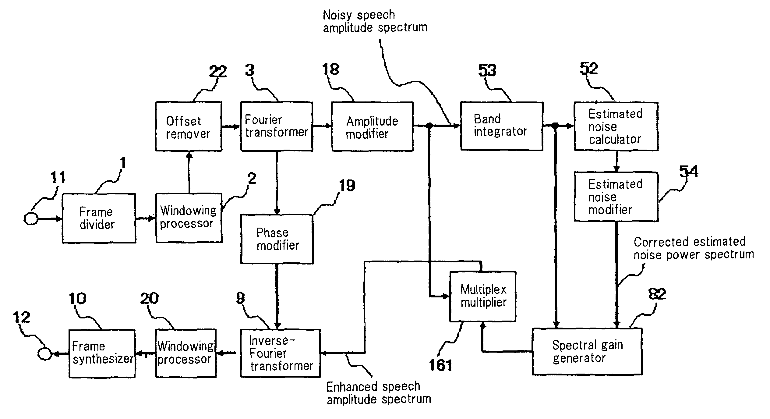
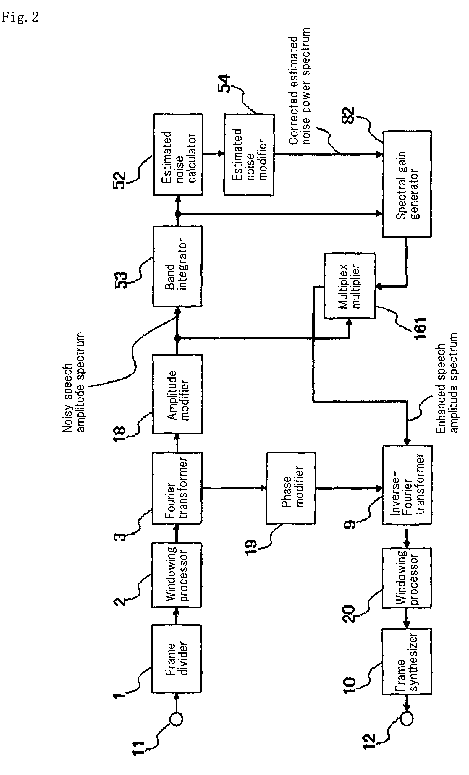
[0105]FIG. 2 is a block diagram showing the present invention.
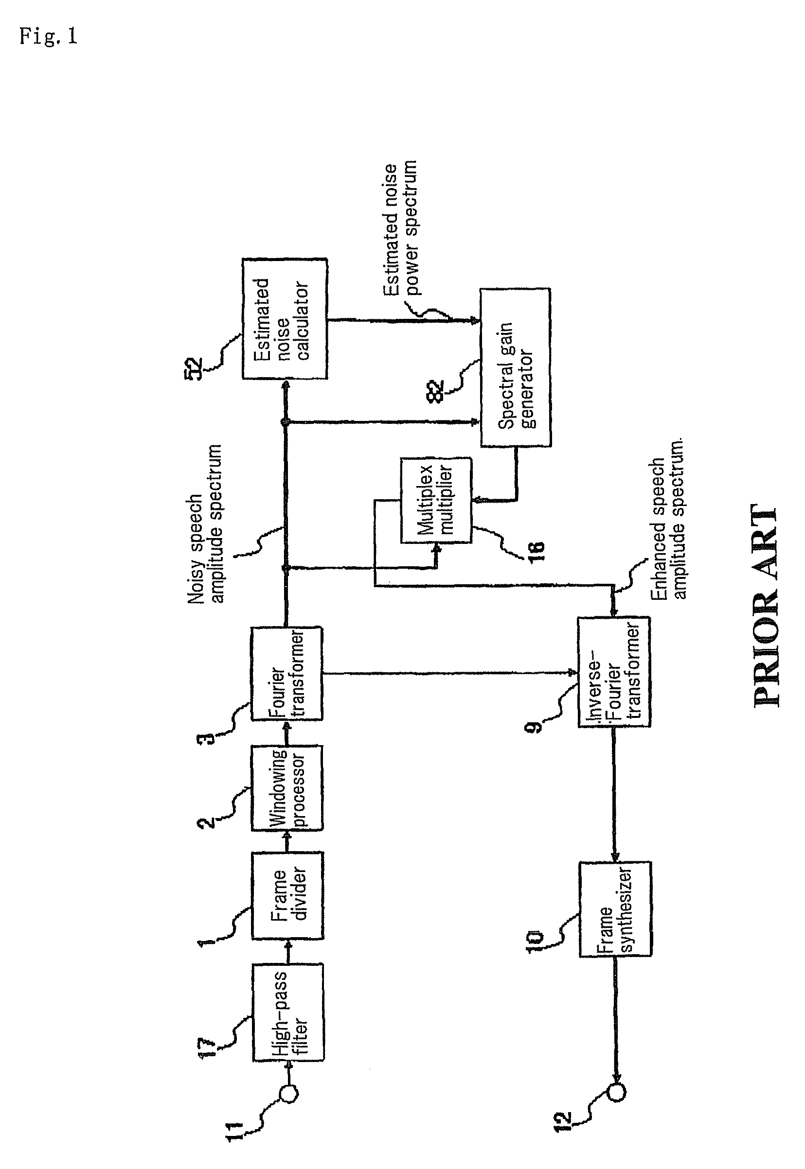
[0106]The configuration shown in FIG. 2 and the conventional configuration shown in FIG. 1 are the same except for high-pass filter 17, amplitude modifier 18, phase modifier 19, windowing processor 20, band integrator 53, estimated noise modifier 54 and multiplex multiplier 161. The detailed operation will be described herein below focusing on these points of difference.
[0107]In FIG. 2, high-pass filter 17 and multiplex multiplier 16 in FIG. 1 are removed, and amplitude modifier 18, phase modifier 19, windowing processor 20, band integrator 53, estimated noise modifier 54 and multiplex multiplier 161 are added instead.
[0108]Amplitude modifier 18 and phase modifier 19 are provided to apply frequency response of a high-pass filter to the signal that was converted into frequency domain. Specifically, in FIG. 2, the absolute value (amplitude-frequency response) of function f which is obtained by applying z=exp(j·2pf) to the t...
third embodiment
[0128]FIG. 8 is a block diagram showing the present invention. A noisy speech signal is supplied to input terminal 11 as a sequence of sample values. The noisy speech signal samples are supplied to frame divider 1 and divided into frames each including K / 2 samples. Here, K is assumed to be an even number. The noisy speech signal samples divided into frames are supplied to windowing processor 2, where the signal is multiplied by window function w(t). Signal yn(t)bar that is windowed by w(t) for input signal yn(t) (t=0, 1, . . . , K / 2−1) of the n-th frame is given as the following equation
[Math 1]
yn(t)=w(t)yn(t) (1)
[0129]It is also a widely used practice for parts of two consecutive frames to be overlapped and windowed. When the overlap length is assumed to be 50% of the frame length, for t=0, 1, . . . , K / 2−1,
[0130]yn(t)bar (t=0, 1, . . . , K−1) obtained from the following equations:
[Math 2]
yn(t)=w(t)yn-1(t+K / 2)
yn(t+K / 2)=w(t+K / 2)yn(t) (2)
is output from windowing processor 2. For...
PUM
 Abstract
Description
Claims
Application Information
 - R&D
- Intellectual Property
- Life Sciences
- Materials
- Tech Scout
- Unparalleled Data Quality
- Higher Quality Content
- 60% Fewer Hallucinations
Browse by: Latest US Patents, China's latest patents, Technical Efficacy Thesaurus, Application Domain, Technology Topic, Popular Technical Reports.
© 2025 PatSnap. All rights reserved.Legal|Privacy policy|Modern Slavery Act Transparency Statement|Sitemap|About US| Contact US: help@patsnap.com


