
Stereoscopic image recognition apparatus

a technology of image recognition and image, applied in the field of stereoscopic image recognition apparatus, can solve the problem that the azimuth-dependent problem of crosstalk cannot be solved, and achieve the effect of solving the reduction of luminance, reducing the color variation of the display screen, and improving crosstalk

Active Publication Date: 2016-04-19
FUJIFILM CORP
View PDF27 Cites 6 Cited by
  • Summary
  • Abstract
  • Description
  • Claims
  • Application Information

AI Technical Summary

Benefits of technology

[0013]In addition, in the stereoscopic image recognition apparatus using two λ / 4 plates, a color variation in a display screen is great, and stereoscopic display (3D display) definition is considerably low even if a luminance variation is reduced when the face is tilted (the time division image display shutter is rotated), as compared with a form which does not use the λ / 4 plate.
[0015]That is to say, an object of the present invention is not only to solve reduction in luminance in a tilted direction caused by employing two λ / 4 plates, and but also to reduce a color variation in a display screen and improve crosstalk. Specifically, an object of the present invention is to provide a stereoscopic image recognition apparatus (a 3D display apparatus) capable of improving a color variation and crosstalk along with viewing angle luminance.
[0016]In addition, another object of the present invention is to provide an optical film which can be manufactured with high yield, and has physical performance sufficient to be used at a foremost surface of a display device. Further, still another object of the present invention is to provide a stereoscopic image recognition apparatus (a 3D display apparatus) with a small viewing angle dependency, and good durability.

Problems solved by technology

Even if a stereoscopic image recognition apparatus is formed by combining the techniques disclosed in JP-A-2002-82307 and JP-A-2004-226945, the azimuth-dependent problem of the crosstalk cannot be solved.

Method used


Image

  • Stereoscopic image recognition apparatus
  • Stereoscopic image recognition apparatus
  • Stereoscopic image recognition apparatus

Examples


examples

[0490]The characteristics of the present invention are described in more detail with reference to Examples and Comparative Examples below. In the following Examples, the amounts of the materials to be used, their ratio, the treatments, their treatment order, and the like may be suitably modified or changed without departing from the sprit and the scope of the present invention. Accordingly, the scope of the present invention shall not be construed to be limited to specific examples shown below.

[0491]1. Preparation of Films 1 to 50

[0492](1) Preparation of Film 1

[0493]1)>

[0494]The following composition was put into a mixing tank and stirred while heating to 30° C. to dissolve the respective components, thereby producing a cellulose acetate solution (a dope A for an inner layer and a dope B for an outer layer).

[0495]

Composition of cellulose acetate solution (parts byInnerOutermass)layerlayerCellulose acetate with acetylation 60.9%100100Triphenyl phosphate (plasticizer) 7.8 7.8Biphenyl ...


PUM

PropertyMeasurementUnit
accurate angleaaaaaaaaaa
angleaaaaaaaaaa
angleaaaaaaaaaa

Abstract

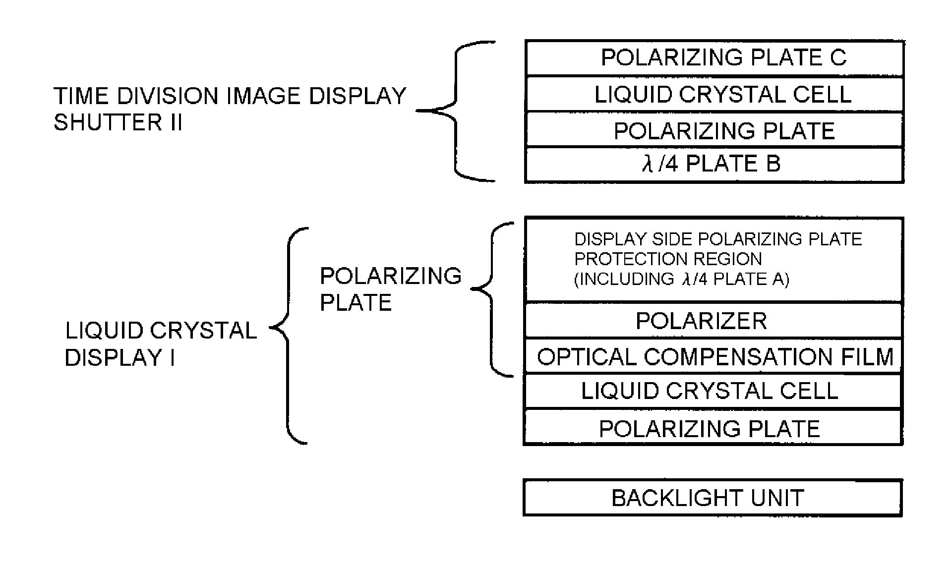
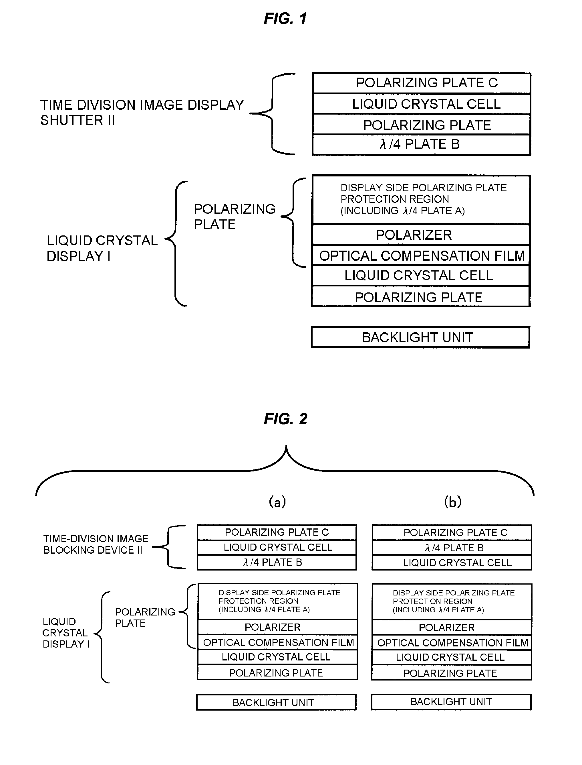
A stereoscopic image recognition apparatus is provided and includes a liquid crystal display I and a time division image display shutter II. The liquid crystal display I includes a λ / 4 plate A in a protection region for a the display side polarizing plate, the protection region being a region on the display side of a polarizer of the one of the polarizing plate. An angle formed by an absorption axis of the display side polarizing plate and a slow axis of the λ / 4 plate A is 35 to 55° or 125 to 145°, and the protection region satisfies |Rth (550)|≦160 nm. The time division image display shutter II includes a polarizing plate C between the second liquid crystal cell and the viewer and includes a λ / 4 plate B between the polarizing plate C and the liquid crystal display I. When the absorption axis of the display side polarizing plate and the absorption axis of the polarizing plate C are disposed so as to be perpendicular or parallel to each other, the slow axes of the λ / 4 plate A and the λ / 4 plate B are perpendicular or parallel to each other.

Description

[0001]This application is based on and claims priority under 35 U.S.C. §119 from Japanese Patent Application Nos. 2010-238033 and 2011-146865, filed Oct. 22, 2010 and Jun. 30, 2011, respectively, the entire disclosures of which are herein incorporated by reference.BACKGROUND OF THE INVENTION[0002]1. Field of the Invention[0003]The present invention relates to a stereoscopic image recognition apparatus capable of improving luminance and enabling an image having a slight color variation to be recognized without crosstalk when a liquid crystal display which projects images displayed in a stereoscopic manner by a time division scheme is viewed in front and obliquely.[0004]2. Background Art[0005]As a stereoscopic image recognition apparatus which has a liquid crystal display mainly including a liquid crystal cell, and a pair of polarizing plates interposing the liquid crystal cell therebetween, and a time division image display shutter which includes a polarizing plate in a form of glass...

Claims


Application Information

Patent Timeline
Patent Type & Authority Patents(United States)
IPC IPC(8): G02B27/22G02F1/13363H04N13/04G02F1/1333G02B30/25
CPCG02B27/2264H04N13/0438G02F1/133634G02F2001/133331G02F2001/133638G02F2413/08G02F2413/11G02B30/24G02F1/133331G02F1/133638H04N13/341
Inventor ISHIGURO, MAKOTO
Owner FUJIFILM CORP
Learn More