
Method, apparatus, and system for production of a stretched film

a production method and film technology, applied in the field of stretched film production methods, can solve the problems of low product yield, poor productivity, disadvantageous image contrast, etc., and achieve the effects of satisfactory optical properties, suppressing temperature variations, and suppressing in-plane retardation ro

Active Publication Date: 2016-04-19
KONICA MINOLTA INC
View PDF14 Cites 0 Cited by
  • Summary
  • Abstract
  • Description
  • Claims
  • Application Information

AI Technical Summary

Benefits of technology

[0049]Owing to the heating portion being arranged so as to face the film being transported in, out of a plurality of zones where temperature control is performed, at least one of the stretching zone and any zone on the downstream side thereof, the film can be heated from its vicinity by the heating portion. Thus, even in a case where a stretched film is produced by transporting a film at high speed, it is possible to suppress unevenness in temperature in the vicinity of the film resulting from the air in an upstream-side zone being drawn into a downstream-side zone as the film is transported. Thus, it is possible to suppress variations in optical values (orientation angle and in-plane retardation Ro) of the film due to such unevenness in temperature.
[0050]In addition, the heating region of the heating portion is provided along a direction intersecting the film transport direction at the intersection angle φ, and by adjusting the intersection angle φ of the heating region according to the orientation angle of the stretched film, even in a case where each film has a different orientation direction, it is possible to adjust the intersection angle φ for each film, and to heat the film evenly in the orientation direction. Thus, it is possible, for each film having a different orientation direction, to obtain a film having satisfactory optical properties with suppressed variations in optical values.

Problems solved by technology

Thus, when external light that has entered the display is reflected on the reflector, the image may disadvantageously have lower contrast.
This disadvantageously results in poor productivity and low product yields due to contamination with shavings.
), the air in an upstream-side zone is drawn into a downstream-side zone as the film is transported, causing unevenness in temperature inside those zones (in particular, in the vicinity of the film), and this unevenness in temperature causes variations in the optical values (orientation angle and in-plane retardation Ro) of the film.
Thus, when the obliquely stretched film is applied to a circular polarizing plate for external light reflection prevention in an image display device with very high contrast, such as a large-screen organic EL television (OLED-TV), reflected external light leaks through the circular polarizing plate to different degrees from place to place over the display screen during display of black, that is, so-called unevenness in the amount of reflected light occurs.
Thus, when the film transport speed is increased, unevenness in temperature in the vicinity of the film cannot be suppressed, and thus variations in optical values cannot be suppressed.

Method used


Image

  • Method, apparatus, and system for production of a stretched film
  • Method, apparatus, and system for production of a stretched film
  • Method, apparatus, and system for production of a stretched film

Examples


example 1-1

Practical Example 1-1

Production Method of a Cycloolefin Film

[0368]In a nitrogen atmosphere, 500 parts of dehydrated cyclohexane was mixed with 1.2 parts of 1-hexene, 0.15 parts of dibutylether, and 0.30 parts of triisobutylaluminum in a reactor vessel at room temperature. Then, while the mixture was kept at 45° C., a norbornene monomer mixture composed of 20 parts of tricyclo[4.3.0.12,5]deca-3,7-diene (dicyclopentadiene, hereinafter abbreviated to DCP), 140 parts of 1,4-methano-1,4,4a,9a-tetrahydrofluorene (hereinafter abbreviated to MTF), and 40 parts of 8-methyl-tetracyclo[4.4.0.12,5.17,10]-dodeca-3-ene (hereinafter abbreviated to MTD) as well as 40 parts of tungsten hexachloride (a 0.7% solution in toluene) were added to the solution continuously for two hours to achieve polymerization. To the polymerized solution, 1.06 parts of butyl glycidyl ether and 0.52 parts of isopropyl alcohol were added to inactivate the polymerization catalyst and stop the polymerization reaction.

[0369]...

example 1-2

Practical Example 1-2

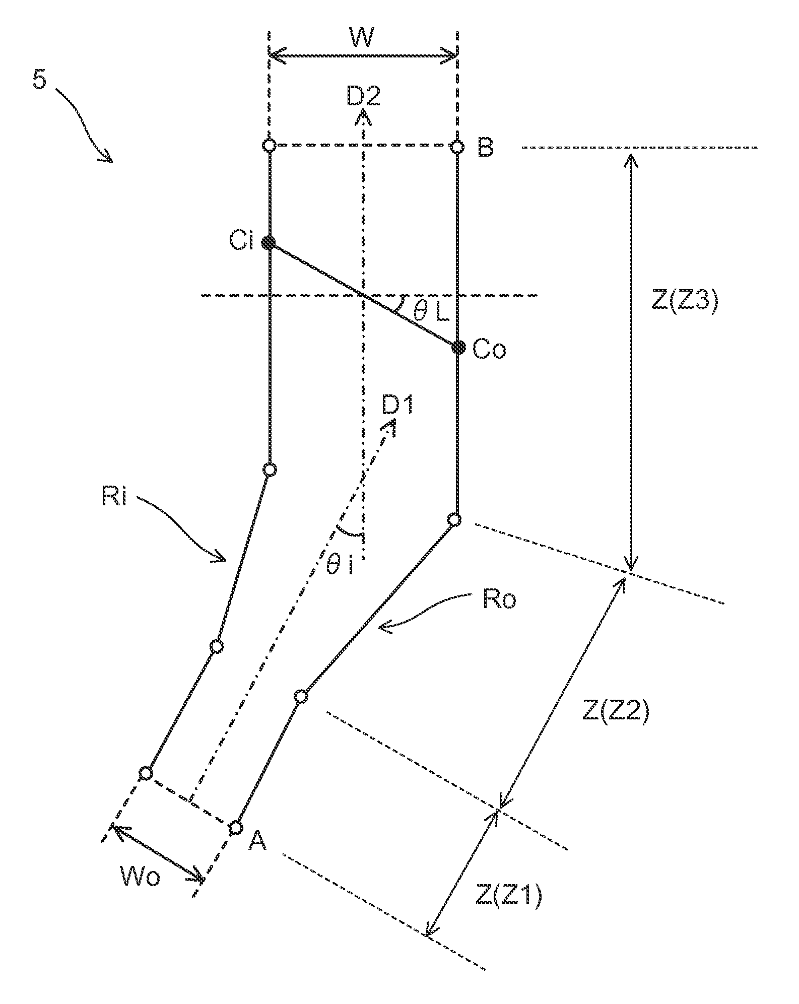
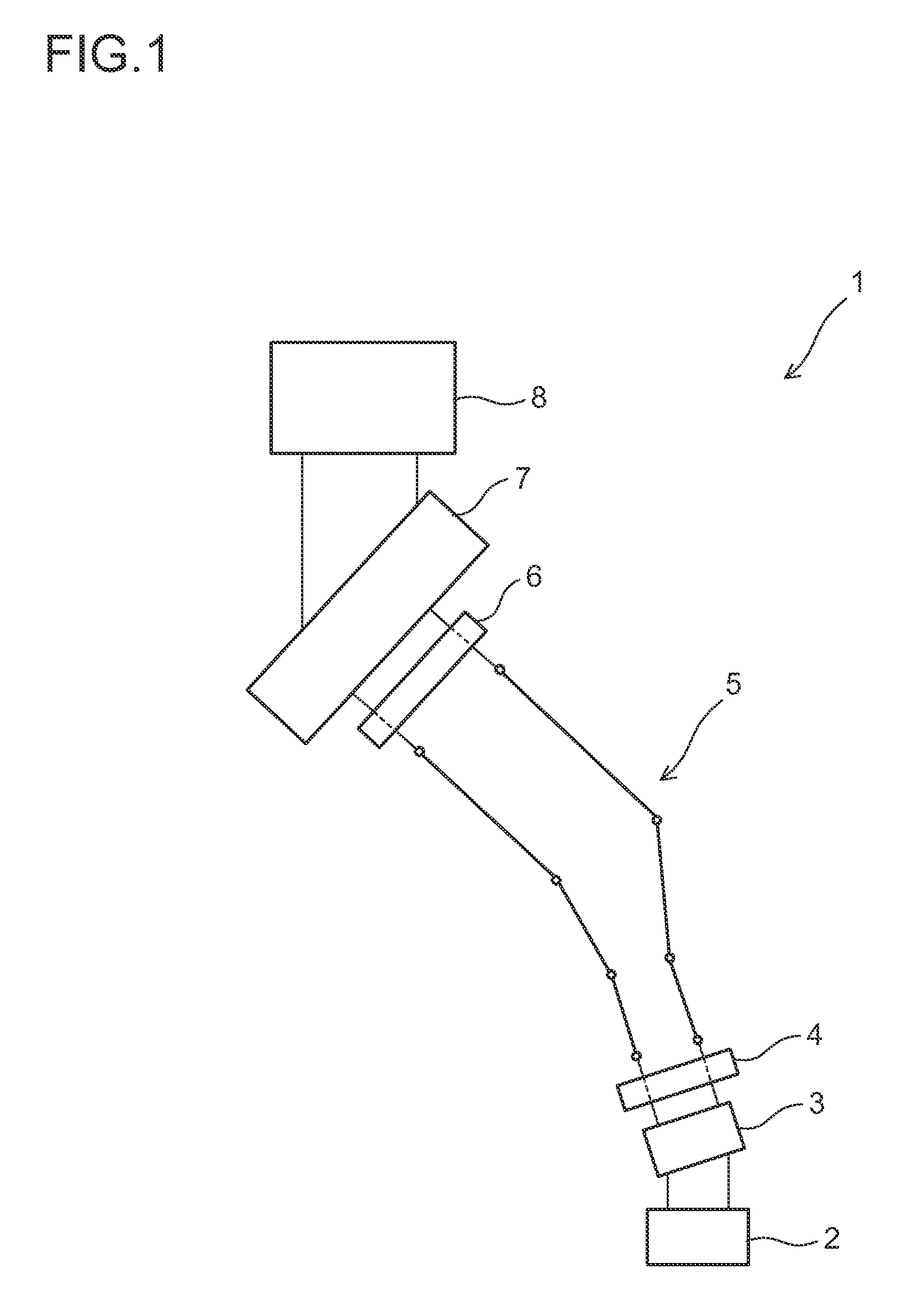
[0389]In Practical Example 1-2, the angle θi between the dispensing direction D1 and the winding direction D2 of the film was changed such that the stretching direction of the film was at 15° relative to the width direction (an orientation angle of 15°). Otherwise, Practical Example 1-2 was the same as Practical Example 1-1.

example 2-1

Practical Example 2-1

[0390]In Practical Example 2-1, as the heating portion 11 arranged in the heat-fixing zone Z3, the halogen lamps 12 shown in FIG. 6 were used to heat the stretched film A′ (with an orientation angle of 45°) in its vicinity. Otherwise, Practical Example 2-1 was the same as Practical Example 1-1.


PUM

PropertyMeasurementUnit
speedaaaaaaaaaa
angleaaaaaaaaaa
angleaaaaaaaaaa

Abstract

In a stretching zone (Z2) included in a plurality of zones for performing temperature control for heating or cooling of a film, the plurality of zones being arranged in the conveyance direction of the film, the film is stretched in a direction tilted in relation to the width direction of the film. The film is heated by a heating unit (11) having a heating region (H) positioned facing the conveyed film and positioned along a direction intersecting at an intersection angle φ with the conveyance direction in the plane of the film, in at least one zone including the stretching zone (Z2) and positioned further downstream in the conveyance direction from the stretching zone (Z2). At this time the intersection angle φ of the heating region (H) is adjusted in accordance with the orientation direction of the film stretched in the stretching zone (Z2).

Description

CROSS REFERENCE TO RELATED APPLICATION[0001]This Application is a 371 of PCT / JP2012 / 057031 filed on Mar. 19, 2012, which is incorporated herein by reference.TECHNICAL FIELD[0002]The present invention relates to a method for production of a stretched film involving stretching a film in a direction oblique to the width direction in a stretching zone, an apparatus for production of a stretched film through such stretching of a film in an oblique direction, and a system for production of a stretched film provided with such a production apparatus.BACKGROUND ART[0003]Stretched films produced by stretching resin are, for their optical anisotropy, used as optical films that perform various optical functions in a variety of display devices. For example, in liquid crystal display devices, a stretched film can be used as an optical compensation film for optical compensation such as coloring prevention, viewing angle enhancement, etc., or a stretched film can be bonded to a polarizer so that th...

Claims


Application Information

Patent Timeline
Patent Type & Authority Patents(United States)
IPC IPC(8): B29C55/00G02B5/30B29C55/04B29D7/01B29C55/12B29K1/00B29K23/00B29L7/00
CPCG02B5/3083B29C55/00B29C55/045B29C55/12B29D7/01B29K2001/08B29K2023/38B29L2007/008G02B5/305
Inventor INAGAKI, SHINJIHOJO, DAISUKEHATAKEYAMA, SHIMPEIUENO, DAISUKENANBU, HIROSHI
Owner KONICA MINOLTA INC
Learn More