
Standoff screening apparatus for detection of concealed weapons

Active Publication Date: 2016-04-19
MOHAMADI FARROKH
View PDF35 Cites 19 Cited by
  • Summary
  • Abstract
  • Description
  • Claims
  • Application Information

AI Technical Summary

Benefits of technology

The patent describes a system for detecting concealed weapons and other contraband using ultra wideband radar sensing and imaging systems. The system uses small scale antennas and is non-invasive of privacy. It can be easily installed and can be used in various security settings such as airports and public buildings. The technical effect of this patent is to provide a reliable and effective solution for detecting hidden threats and ensuring public safety.

Problems solved by technology

An important security issue for protection of individuals in public places—such as public gatherings, voting lines, entrances of stadiums, government agency offices, religious gathering places, banks, markets, airports, schools, and government facilities, for example—is detection of hidden objects, e.g., objects such as weapons or improvised explosive devices (IED) that may be carried by a person and concealed, for example, underneath or within clothing or in luggage or other hand-carried items.
X-ray technology has been used, for example, for airport screening but presents a number of issues, such as cumulative over exposure to radiation for airport and airline personnel and concerns over personal privacy, that have led to a search for other technologies and methods for addressing these security issues.

Method used


Image

  • Standoff screening apparatus for detection of concealed weapons
  • Standoff screening apparatus for detection of concealed weapons
  • Standoff screening apparatus for detection of concealed weapons

Examples


Embodiment Construction

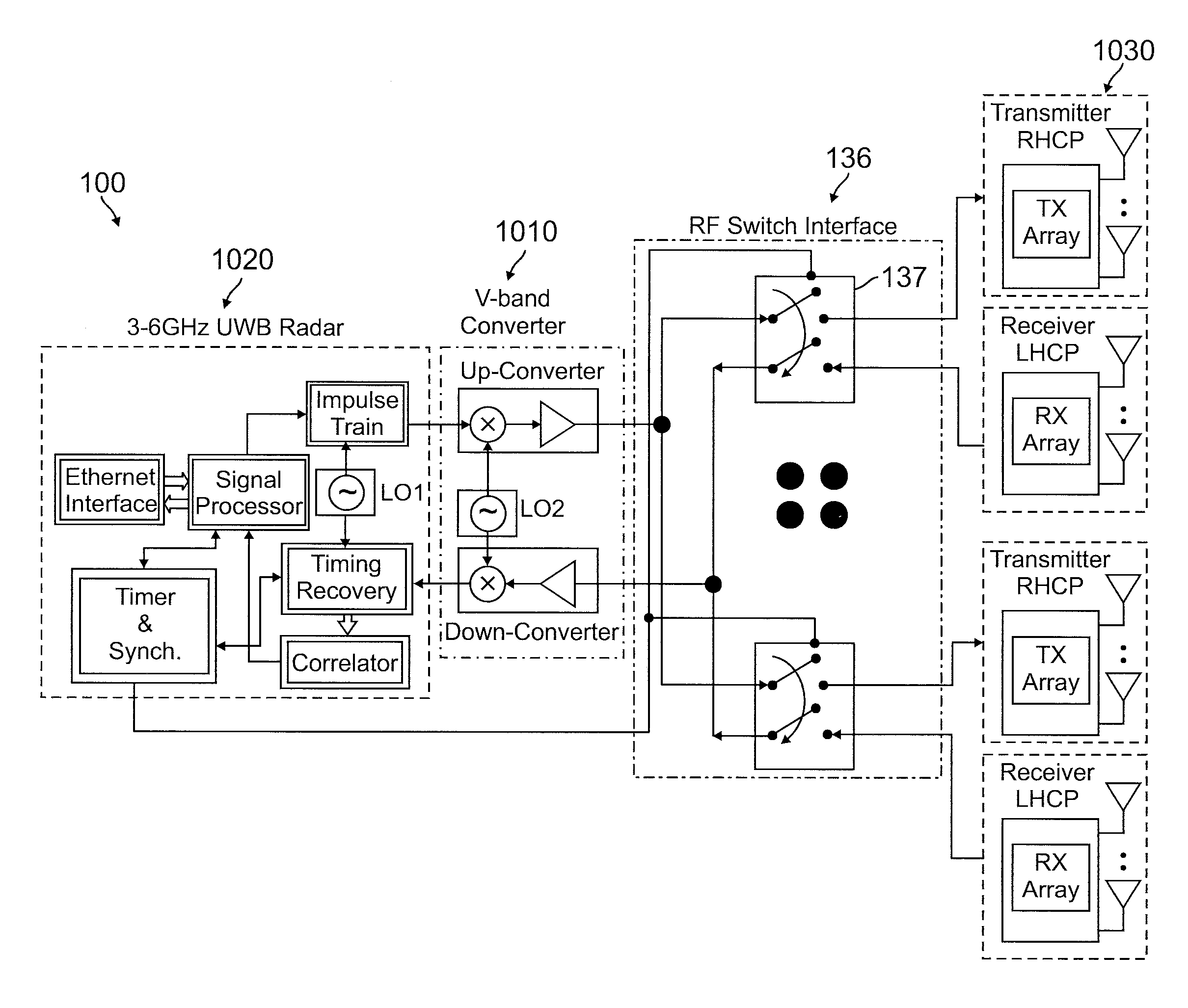
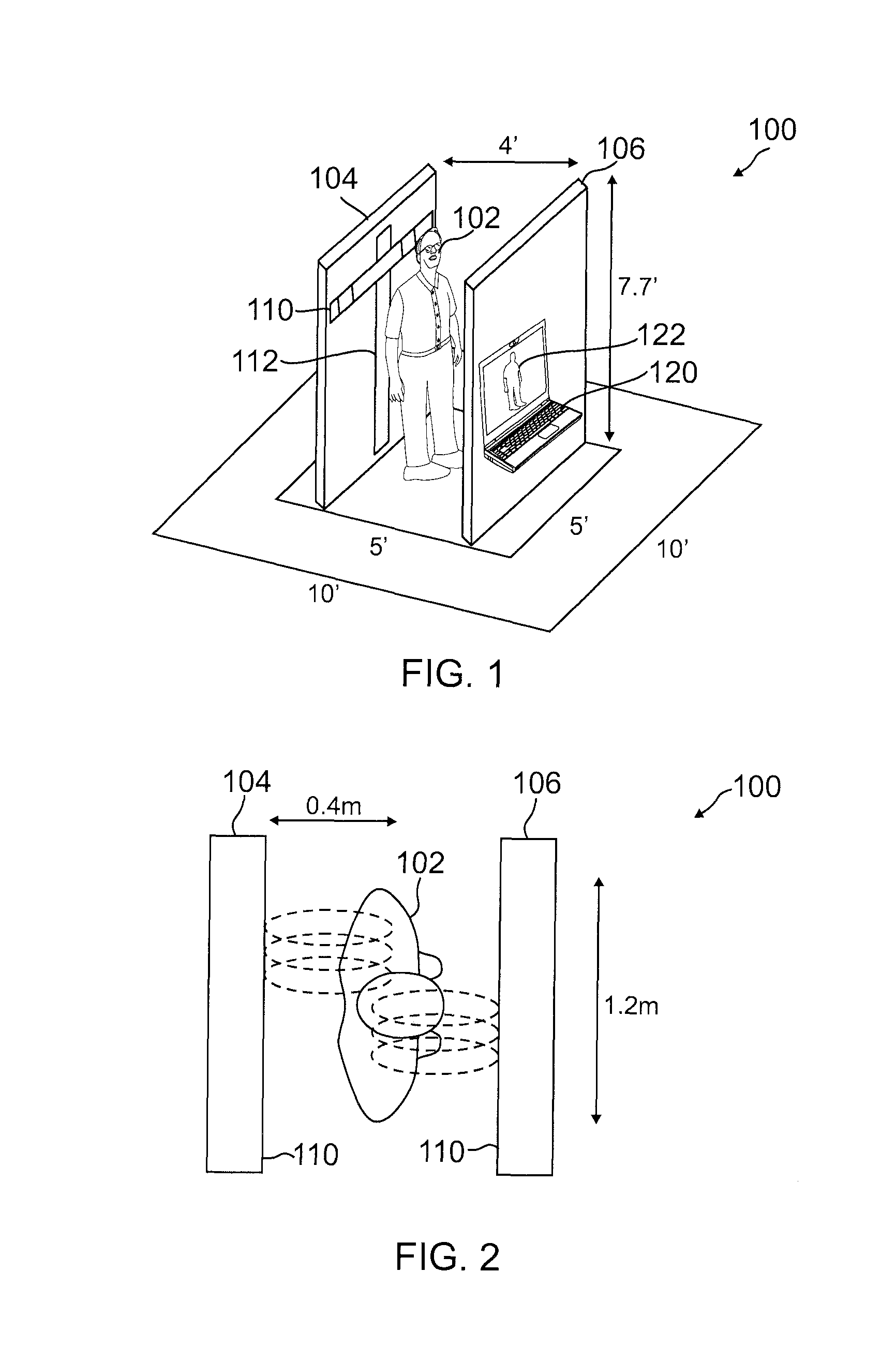
[0019]Broadly speaking, methods and systems are provided in one or more embodiments for detecting concealed weapons and other contraband using ultra wideband (UWB) radar sensing and imaging systems that employ wafer scale (e.g., less than 2.0 inches in side dimension for the antenna array) active array antennas. Such small scale UWB radar sensing and imaging systems can find application to many types of security concerns, such as screening people for concealed weapons (including non-metallic weapons) or explosives at airports and other public buildings. One or more embodiments may provide a walk-through scanning station for screening individuals that can detect, for example, an improvised explosive device (IED) concealed on a person, yet may be considered as being non-invasive of privacy. The scanning station may employ an easy-to-set-up pair of panels that may require no more than 15 minutes of installation time in order to be ready to be used and that may be readily deployed, for ...


PUM


Abstract

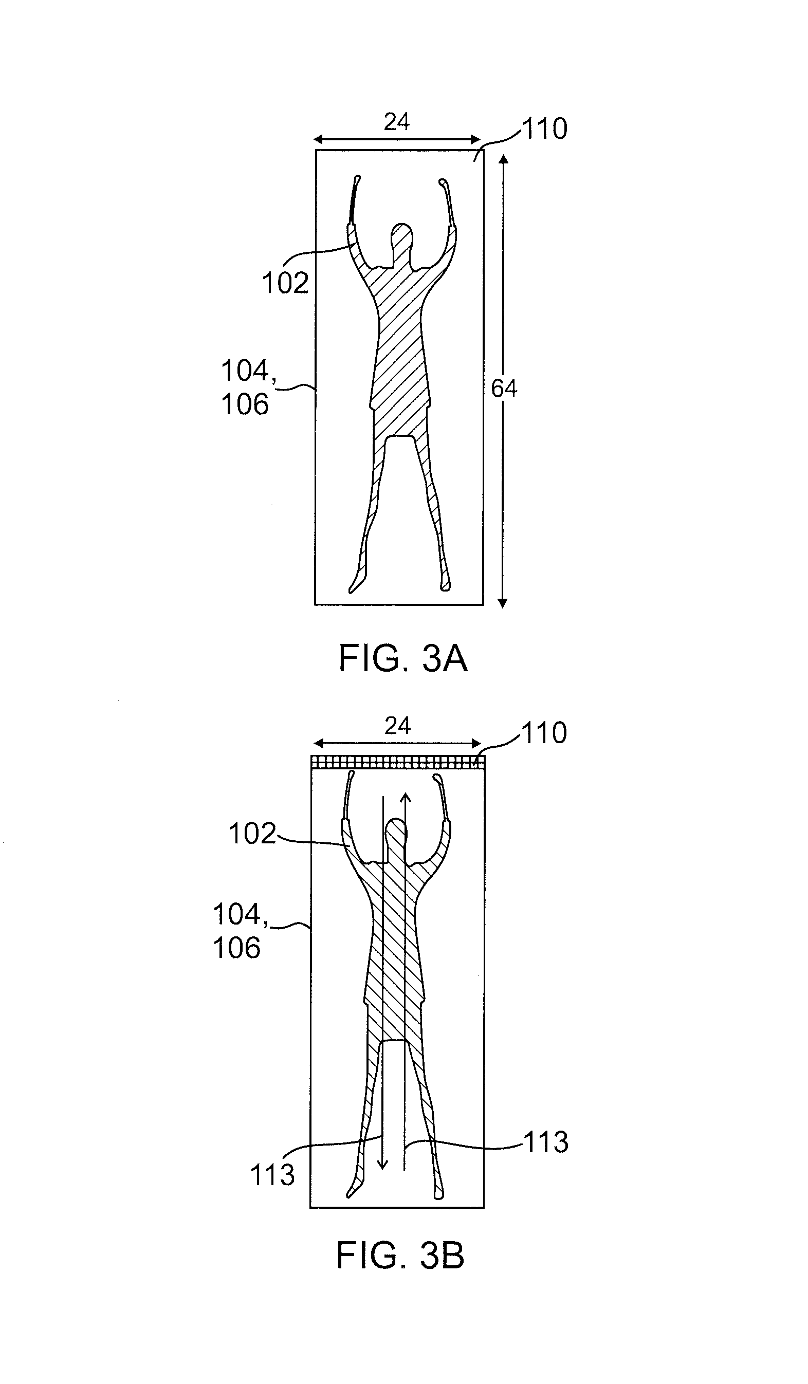
A walk-through screening station scans individuals to detect contraband such as a concealed weapon or improvised explosive device (IED) using ultra wideband (UWB) radar sensing and imaging systems employing wafer scale active array antennas. UWB radar and advanced imaging technology enable automated threat recognition and display for monitoring personnel. The station may scan subjects passing close to or within an aperture width of an array of radar transceivers. Direct calibration by use of reflectors positioned at known locations in the image may be used to implement scanning and imaging so close to the array. The scanning station may employ an easy-to-set-up pair of panels that may be readily deployed by security providers wherever access control—such as to a meeting place or transportation boarding—is needed. Imaging and display processing may provide an abstract display—such as a stick figure representation of anatomy—to address privacy issues and concerns.

Description

CROSS REFERENCE TO RELATED APPLICATIONS[0001]This application claims the benefit of priority from U.S. Provisional Patent Application No. 61 / 620,802, filed Apr. 5, 2012, which is incorporated by reference.BACKGROUND[0002]1. Technical Field[0003]Embodiments of the present invention generally relate to radar imaging systems and, more particularly, to security screening of individuals using ultra wideband radar incorporating integrated wafer scale, right hand circularly polarized (RHCP) and left hand circularly polarized (LHCP) antenna arrays.[0004]2. Related Art[0005]An important security issue for protection of individuals in public places—such as public gatherings, voting lines, entrances of stadiums, government agency offices, religious gathering places, banks, markets, airports, schools, and government facilities, for example—is detection of hidden objects, e.g., objects such as weapons or improvised explosive devices (IED) that may be carried by a person and concealed, for exampl...

Claims


Application Information

Patent Timeline
IPC IPC(8): G01S13/88G01S13/89G01S7/41G01S13/04G01S7/02
CPCG01S7/411G01S13/89G01S13/887G01S7/024G01S13/04H01Q21/0075H01Q21/061G01S7/026G01S13/0209G01S7/06
Inventor MOHAMADI, FARROKH
Owner MOHAMADI FARROKH
Learn More