
Electrical connector

a technology of electrical connectors and connectors, applied in the direction of coupling device connections, coupling protective earth/shielding arrangements, two-part coupling devices, etc., can solve the problems of high frequency problem, inability to ensure the shielding effect, and inability to snap-fit the connector and the insulation body. , to achieve the effect of preventing abrasion problems, ensuring the shielding effect, and stable buckling

Active Publication Date: 2016-03-29
LOTES
View PDF4 Cites 60 Cited by
  • Summary
  • Abstract
  • Description
  • Claims
  • Application Information

AI Technical Summary

Benefits of technology

[0007]In one aspect, the present invention is directed to an electrical connector which achieves abrasion prevention and stable snap-fit and fixing by means of buckling between a middle shielding sheet and a mating connector.
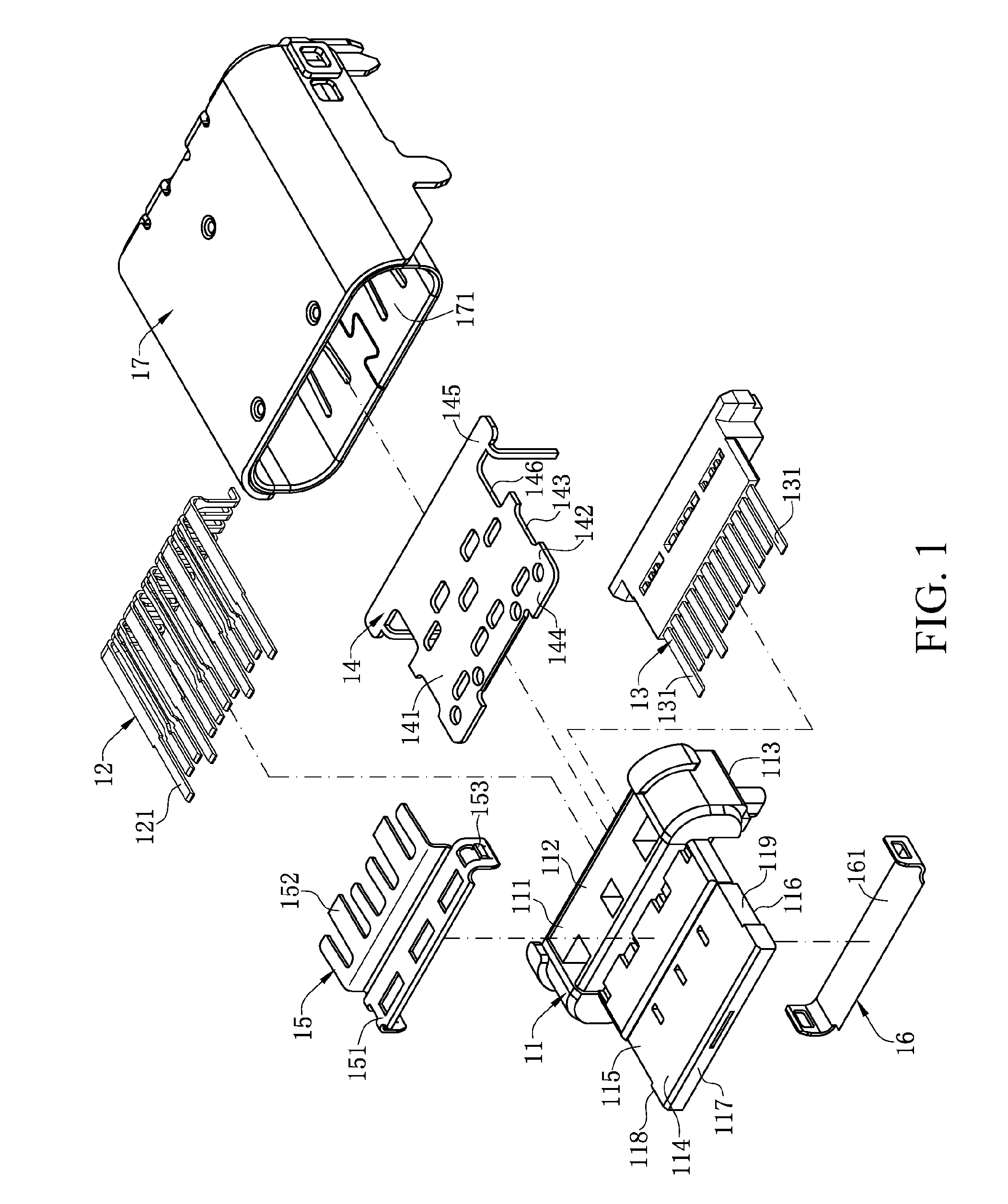
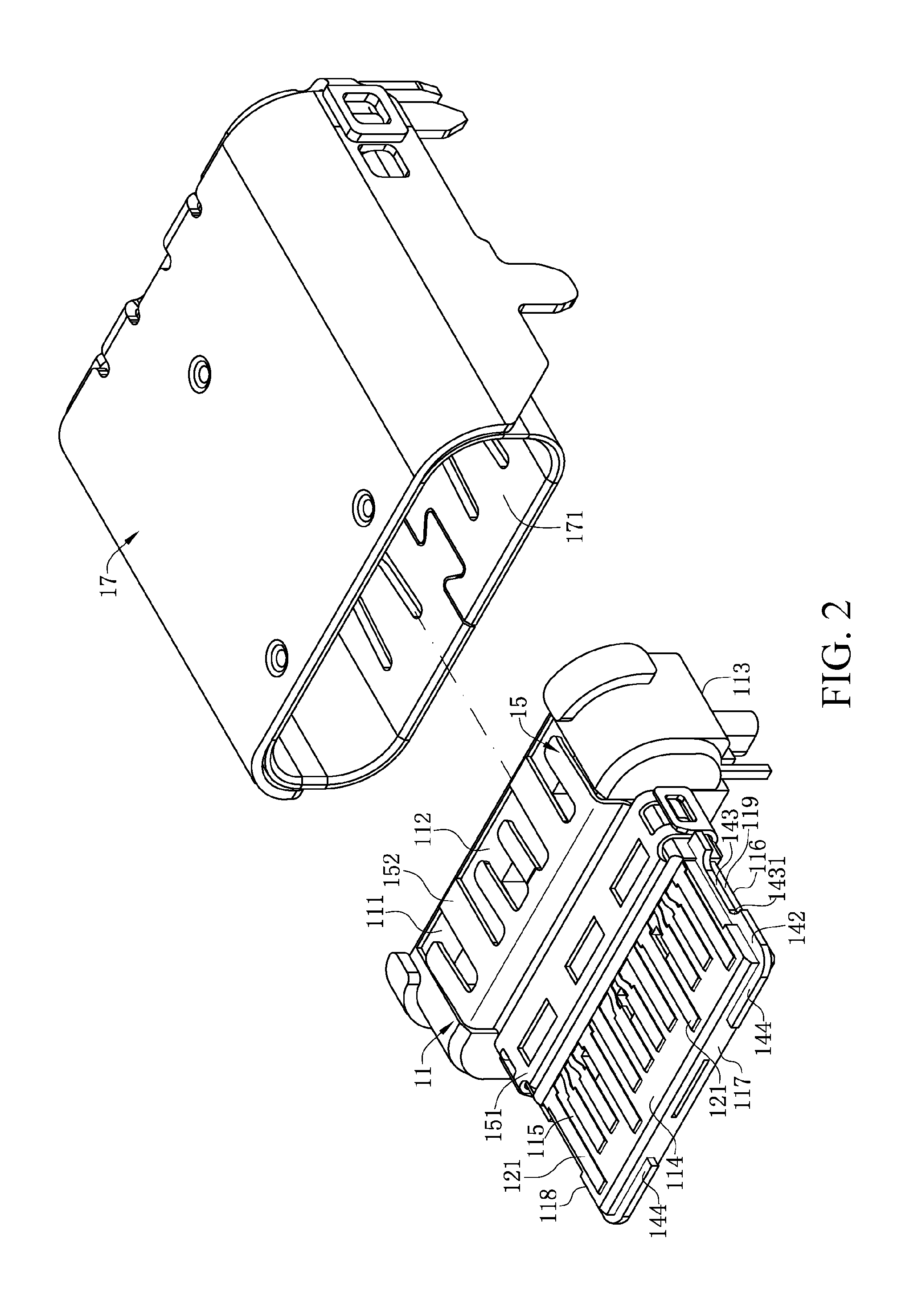
[0016]Compared with the related art, in certain embodiments of the present invention, the groove disposed on the middle shielding sheet is exposed from a side of the tongue. Both the middle shielding sheet and the metal elastic sheet are made of metal material. When the mating connector enters the mating cavity, the metal elastic sheet and the groove are fixed in a snap-fit manner, which ensures stable buckling between the mating connector and the electrical connector, and prevents abrasion problem.
[0017]Additionally, in such a snap-fit manner described above, the metal casing of the electrical connector does not need to be particularly provided with a snap-fit elastic sheet. Therefore, the shielding effect can be ensured. Meanwhile, the middle shielding sheet is disposed to further isolate the upper row of terminals from the lower row of terminals, thereby preventing signal interference between terminals.

Problems solved by technology

Because the mating connector and the insulation body are both made of plastic material, abrasion easily occurs after the mating connector and the insulation body are cooperatively fixed multiple times, resulting in unstable snap-fit between the mating connector and the insulation body.
When the mating connector is made of metal material, more severe abrasion occurs in the snap-fit slot or snap-fit portion because of the cooperation between the metal material and the plastic material.
The snap-fit manner solves the problem that abrasion causes unstable snap-fit, but because the metal elastic sheet is disposed on the metal casing, a hole or slot is inevitably provided correspondingly.
As signal transmission of electronic elements is increasingly faster currently, a high frequency problem needs to be considered for an electrical connector.
Therefore, a heretofore unaddressed need exists in the art to address the aforementioned deficiencies and inadequacies.

Method used


Image

  • Electrical connector
  • Electrical connector
  • Electrical connector

Examples


Embodiment Construction

[0025]The present invention is more particularly described in the following examples that are intended as illustrative only since numerous modifications and variations therein will be apparent to those skilled in the art. Various embodiments of the invention are now described in detail. Referring to the drawings, like numbers indicate like components throughout the views. As used in the description herein and throughout the claims that follow, the meaning of “a”, “an”, and “the” includes plural reference unless the context clearly dictates otherwise. Also, as used in the description herein and throughout the claims that follow, the meaning of “in” includes “in” and “on” unless the context clearly dictates otherwise. Moreover, titles or subtitles may be used in the specification for the convenience of a reader, which shall have no influence on the scope of the present invention.

[0026]It will be understood that when an element is referred to as being “on” another element, it can be di...


PUM


Abstract

An electrical connector for mating with a mating connector having a metal elastic sheet. The electrical connector includes an insulating body, a middle shielding sheet and a metal casing. The insulating body includes a base, a tongue extending forward from the base, and an upper row and a lower row of terminals. Each upper and lower row terminals has a contact portion exposed from upper and lower surfaces of the tongue respectively. The middle shielding sheet is disposed in the tongue and located between the upper row and lower row of terminals. The middle shielding sheet includes a groove exposed from a side of the tongue, for being buckled by the metal elastic sheet to stop forward displacement of the metal elastic sheet. The metal casing wraps a periphery of the insulation body to form a mating cavity, for the mating connector to be entered therein.

Description

CROSS-REFERENCE TO RELATED APPLICATION[0001]This application claims priority to and the benefit of, pursuant to 35 U.S.C. §119(e), U.S. provisional patent application Ser. No. 61 / 942,830, filed Feb. 21, 2014, entitled “ELECTRICAL CONNECTOR,” by Chin Chi Lin, which is incorporated herein in its entirety by reference.[0002]Some references, if any, which may include patents, patent applications and various publications, may be cited and discussed in the description of this invention. The citation and / or discussion of such references, if any, is provided merely to clarify the description of the present invention and is not an admission that any such reference is “prior art” to the invention described herein. All references listed, cited and / or discussed in this specification are incorporated herein by reference in their entireties and to the same extent as if each reference was individually incorporated by reference.FIELD OF THE INVENTION[0003]The present invention relates to an electri...

Claims


Application Information

Patent Timeline
Patent Type & Authority Patents(United States)
IPC IPC(8): H01R13/648H01R13/426H01R13/6585H01R24/60
CPCH01R24/60H01R13/426H01R13/6585
Inventor LIN, CHIN, CHIJU, TEDPENG, ZHI, GUO
Owner LOTES
Learn More