
Power line communication system

a technology of power line communication and communication system, which is applied in the direction of amplitude-modulated carrier system, transmission, efficient power electronics conversion, etc., can solve the problems of compromising the privacy of communication, and achieve the effect of high frequency switching capability, reduced noise background, and easy scaling

Inactive Publication Date: 2016-03-22
LED DRIVEN HLDG
View PDF4 Cites 2 Cited by
  • Summary
  • Abstract
  • Description
  • Claims
  • Application Information

AI Technical Summary

Benefits of technology

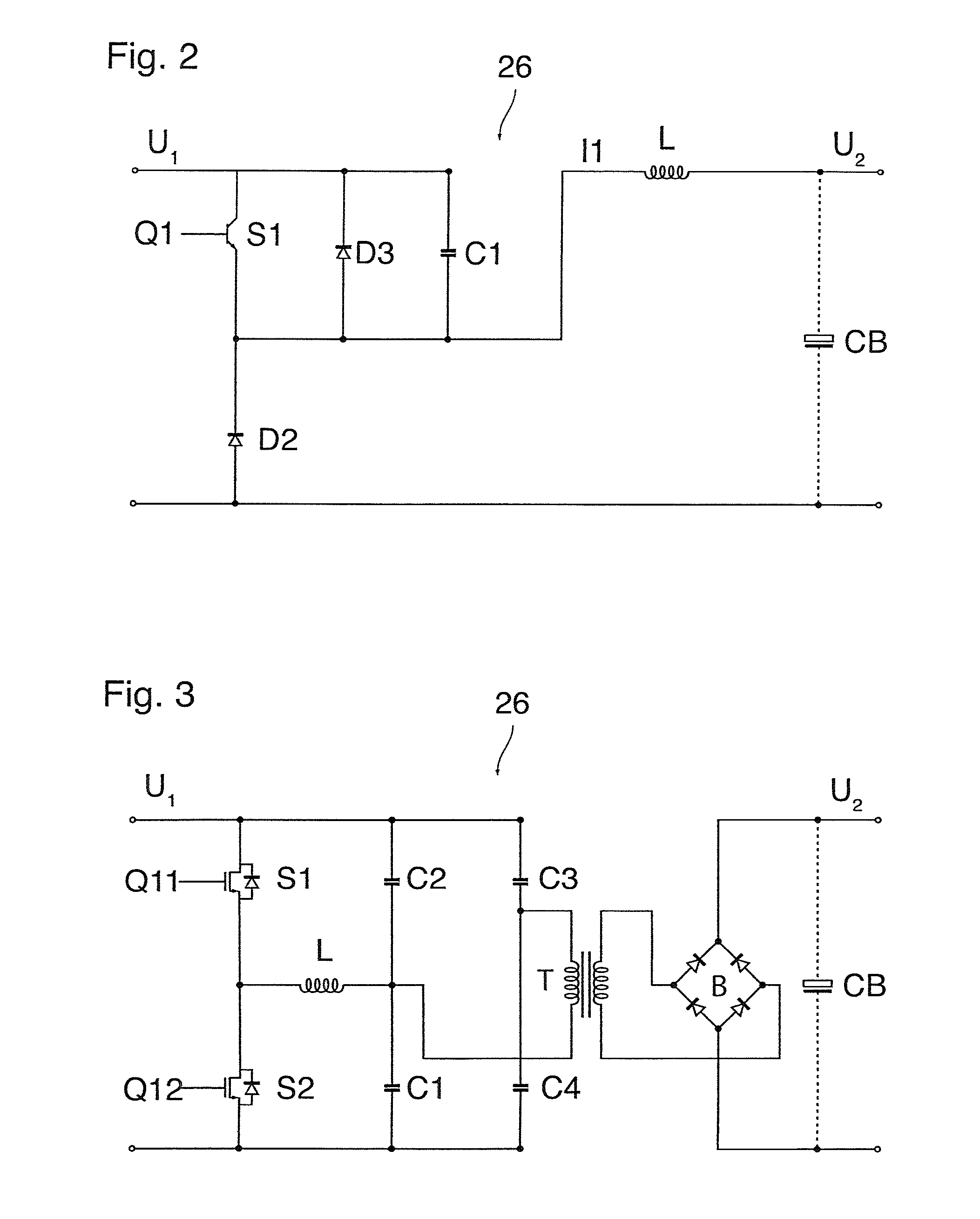
The invention describes a system for power line communication without the need for a specific modulator. The modulation is based on the high frequency switching capabilities of the controller that drives the converters. This allows for a natural PLC modulation frequency, reducing noise in the background. The system can be easily scaled by adding more converters to increase power supply or signal to noise ratio. The system uses self-tuning receivers that automatically tune to a fixed frequency component. The power supply circuit is a multi-stage converter with a first stage for voltage conversion and a second stage for interleaved switching of converters. The controller switches between balanced and unbalanced modes for optimal switching losses.

Problems solved by technology

A general problem in conjunction with power line communication is to control the range of the communication signals such that, on the one hand, all connected receivers can safely receive the messages with a sufficient signal to noise ratio and, on the other hand, the signals are not spread so far over the power grid that privacy of the communication is compromised.

Method used


Image

  • Power line communication system
  • Power line communication system
  • Power line communication system

Examples


Embodiment Construction

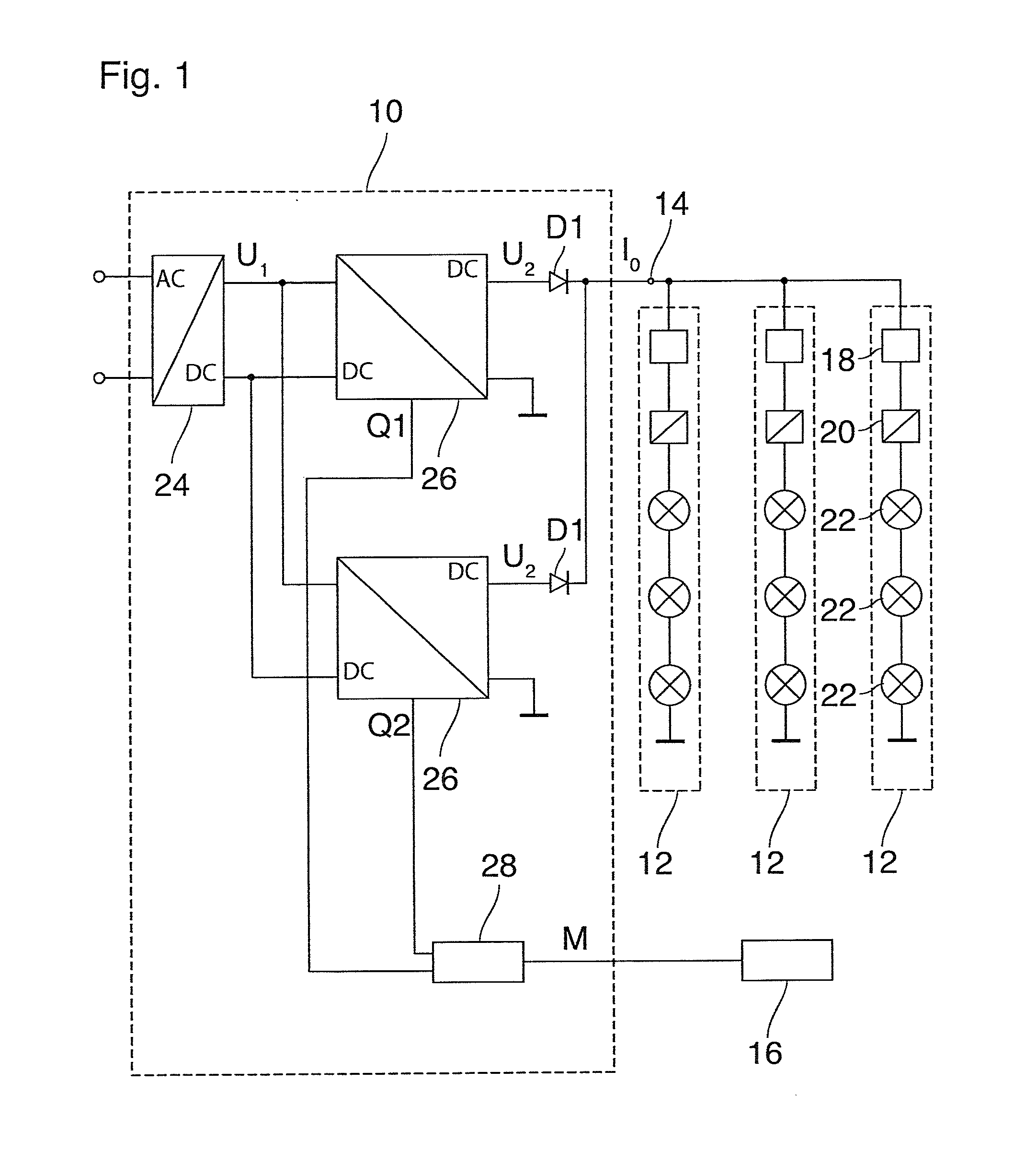
[0037]In the example shown in FIG. 1 the power line communication system forms part of a lighting system that includes a power supply circuit 10 and a number of parallel load circuits 12, three in this example, that are connected to an output terminal 14 of the power supply circuit 10. A PLC transmitter 16 is connected to the power supply circuit 10, and each load circuit 12 includes a PLC receiver 18 controlling a DC / DC converter 20, and a string of LEDs 22. The DC / DC converter 20 permits to switch on and off and to dim the string of LEDs 22 in accordance with signals received by the PLC receiver 18.

[0038]The PLC transmitter 16 is capable of sending digital messages to the PLC receivers 18 by modulating a current I0 that is supplied to the load circuits 12 via the output terminal 14. In a commissioning step, a digital address has been assigned to each of the receivers 18. Each digital message sent to the receivers 18 has the form of a bit sequence that includes an address part and ...


PUM


Abstract

A power supply circuit includes a number N, N≧2, of parallel connected, cyclically switched electronic converters having outputs connected to a common output terminal; and a controller providing switching pulse signals switching the converters with a switching frequency that is the same for all converters; load circuits connected to the output terminal; a PLC transmitter modulating an output current from the output terminal; and a PLC receiver in each load circuit, the controller switching the converters with interleaved switching pulse signals; the PLC transmitter modulating the output current by switching the controller between at least two modes of operation that differ in phase relations and / or pulse shapes of the switching pulse signals, changing a ripple frequency spectrum of the output current such that a suppression amount of a predetermined frequency component is changed depending upon the mode of operation; and the PLC receiver detects the predetermined frequency component.

Description

BACKGROUND OF THE INVENTION[0001]The invention relates to a power line communication (PLC) system comprising[0002]a power supply circuit comprising[0003]a number N, N≧2, of cyclically switched electronic converters connected in parallel and having respective outputs connected to a common output terminal of the power supply circuit; and[0004]a controller providing switching pulse signals for switching the converters with a switching frequency that is the same for all converters;[0005]at least one load circuit connected to the output terminal of the power supply circuit;[0006]a PLC transmitter arranged to modulate an output current from the output terminal of the power supply circuit; and[0007]a PLC receiver in said at least one load circuit.[0008]In a power line communication (PLC) system, a power line that connects an electric power source to a consumer is used for transmitting signals in addition to the electric power, for example for the purpose of remote control of the consumer. ...

Claims


Application Information

Patent Timeline
IPC IPC(8): H04B3/54H04B1/16H04B1/04
CPCH04B3/542H04B1/04H04B1/16H02M1/15H02M3/157H02M3/285H02M3/33515H04B3/548H04L27/04H04B2203/5412H04B2203/5445H04B2203/547H04L27/30H04L25/0286Y02B70/10H02M1/0058H02M3/1586H02M1/0043H02M3/01H02M3/33571
Inventor VAN CASTEREN, DOLFGRONINGER, MARKKARDOLUS, MENNO
Owner LED DRIVEN HLDG
Learn More