
Method and apparatus for maintaining microcarrier beads in suspension

a microcarrier and suspension technology, applied in the field of biotechnology, can solve the problems of complex design and maintain optimal growth, and achieve the effect of facilitating ease and cost of production, enhancing agitation and mixing of growth medium

Active Publication Date: 2016-03-01
GLOBAL LIFE SCI SOLUTIONS OPERATIONS UK LTD
View PDF24 Cites 4 Cited by
  • Summary
  • Abstract
  • Description
  • Claims
  • Application Information

AI Technical Summary

Benefits of technology

[0017]Bioreactors are usually cylindrical in shape, typically ranging from one liter to several hundred liters in capacity. They are usually made of glass or stainless steel, so that they are chemically and biologically inert and allowing them to be sterilised (e.g. by autoclaving). Their design can be complex to maintain optimum growth conditions such as dissolved oxygen levels (using gases such as air, oxygen, nitrogen), pH (using carbon dioxide and sodium bicarbonate) and temperature control. A key element is the agitation which allows cells to be maintained in suspension without suffering damage through agitation and / or physical abrasion.
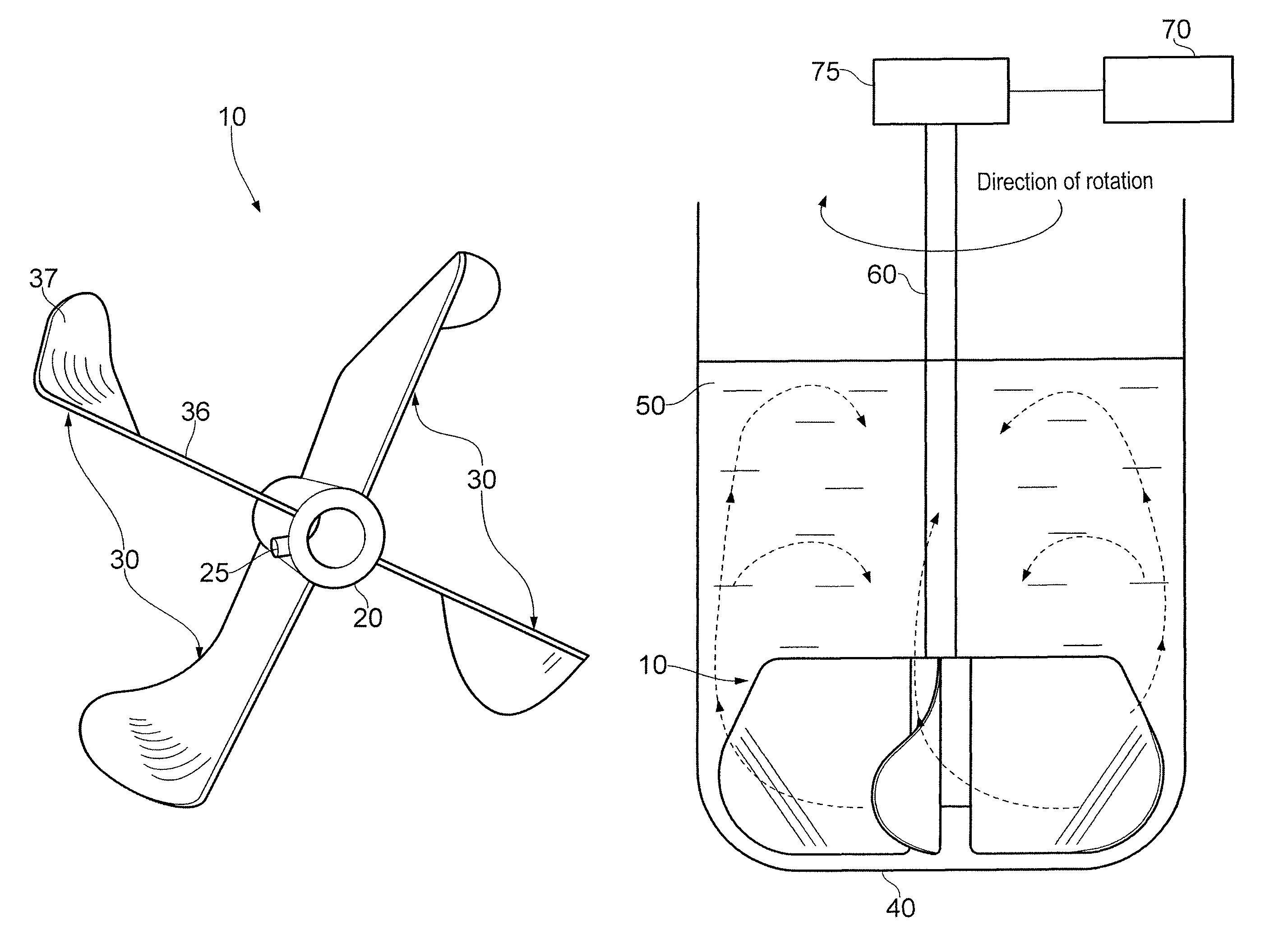
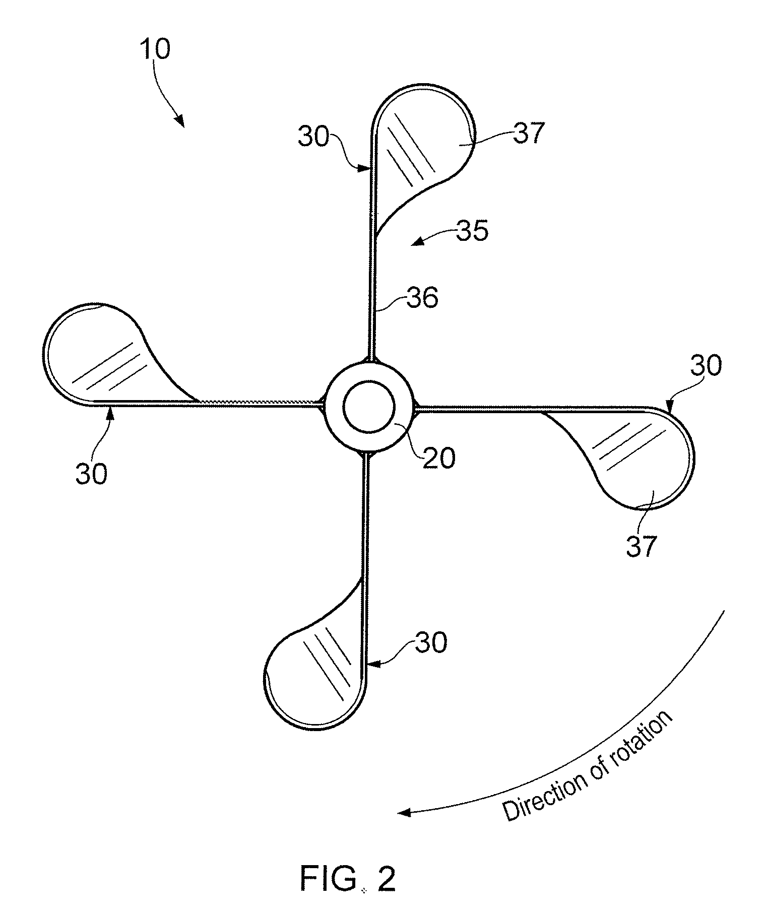
[0022]In a further aspect, the curved portion (37) is curved upwards to enhance the agitation and mixing of the growth medium.
[0023]In one aspect, each blade (30) is reversibly attached to the hub (20). This allows the user to replace damaged or worn blades, or to change the size of blades for bioreactors or cell separators of different volumes.
[0024]In another aspect, each blade (30) is irreversibly attached to the hub (20) to facilitate ease and cost of production.
[0031]In another aspect, the growth medium contains microcarrier beads and the cells attach to the beads while the impeller is stirring the growth medium. This obviates the need to seed microcarrier beads with cells prior to addition to the growth medium and thus saves user time and simplifies the work flow.

Problems solved by technology

Their design can be complex to maintain optimum growth conditions such as dissolved oxygen levels (using gases such as air, oxygen, nitrogen), pH (using carbon dioxide and sodium bicarbonate) and temperature control.

Method used


Image

  • Method and apparatus for maintaining microcarrier beads in suspension
  • Method and apparatus for maintaining microcarrier beads in suspension
  • Method and apparatus for maintaining microcarrier beads in suspension

Examples


Embodiment Construction

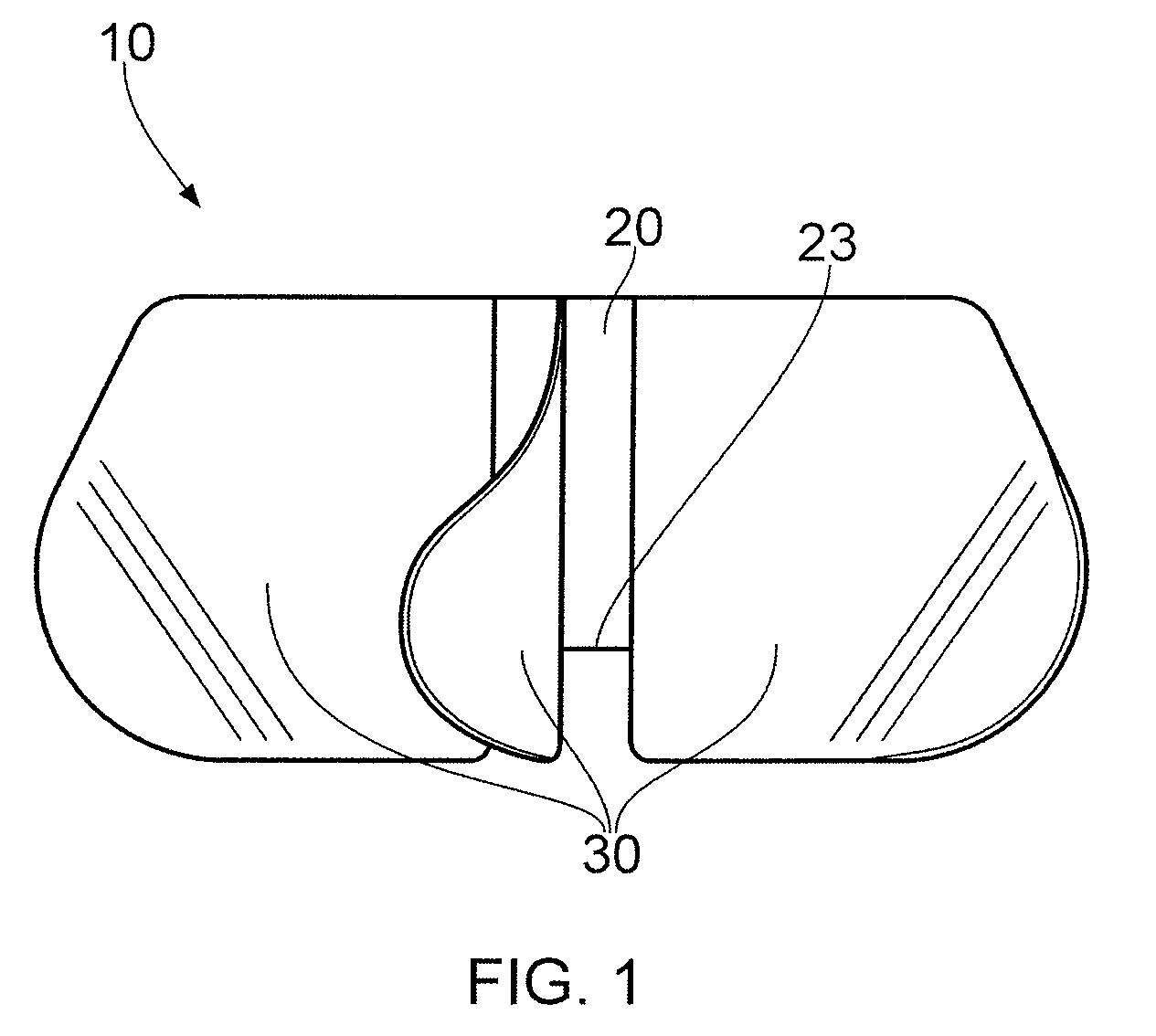
[0052]Referring now to FIGS. 1, 2 and 3, there is shown an embodiment of the impeller (10) in side view, in plan view, and in plan perspective, respectively. The impeller includes four blades (30) (three being shown in FIG. 1, the fourth extending into the plane of the paper) each impeller blade being mounted onto a hub (20) which is rotatable on a shaft (not shown) which, in turn is rotated by suitable means, for example an electric motor (not shown). In this embodiment, each of the impeller blades (30) are radially disposed around the circumference of the hub (20) at 90° intervals from each other.

[0053]In one embodiment (as shown in FIG. 1), each impeller blade (30) may extend to the same extent and a little below the end portion (23) of the impeller hub (20). In another embodiment, the lower end of the impeller hub (23) is in line with the lower edge of each blade.

[0054]In one embodiment, the shaft is dimensioned to be a friction fit inside the hub (20) of the impeller (10) and m...


PUM

PropertyMeasurementUnit
thicknessaaaaaaaaaa
thicknessaaaaaaaaaa
widthaaaaaaaaaa

Abstract

The invention relates to an impeller for use in a bioreactor for growing adherent mammalian cells and / or a cell separator for adherent mammalian cells. The impeller of the invention is designed to efficiently and rapidly lift a bed of settled cells and microcarrier beads at low rotational speeds. Cell growth and concomitant yield is therefore improved by maintaining the culture in an environment of low shear force.

Description

CROSS-REFERENCE TO RELATED APPLICATIONS[0001]This application is a filing under 35 U.S.C. §371 and claims priority to international patent application number PCT / EP2010 / 055477 filed Apr. 23, 2010, published on Nov. 4, 2010 as WO 2010 / 125006, which claims priority to application number 0907260.4 filed in Great Britain on Apr. 28, 2009.FIELD OF THE INVENTION[0002]The present invention relates to the fields of biotechnology, especially the field of tissue culture. In particular, the invention relates to an impeller for stirring microcarrier beads within a liquid culture suspension to enable the growth and processing of anchorage-dependent or adherent mammalian cells.BACKGROUND TO THE INVENTION[0003]The development of High Throughput Screening (HTS) assay procedures for the identification of potential drug candidates has established the need for large numbers of cells for each type of test. As a consequence there is a significant challenge to overcome the “culturing burden” to enable mu...

Claims


Application Information

Patent Timeline
Patent Type & Authority Patents(United States)
IPC IPC(8): B01F7/22C12M1/06C12M1/00B01F7/18B01F7/00B01F27/91
CPCB01F7/00275B01F7/22C12M27/02C12M29/04C12M47/12B01F7/18B01F27/1123B01F27/90B01F27/91
Inventor JONES, CHRISTOPHERMEYLER, PHILIP, JOHNEVANS, RHYS
Owner GLOBAL LIFE SCI SOLUTIONS OPERATIONS UK LTD
Learn More