
Flow control assembly for a fire sprinkler system

a flow control and sprinkler technology, applied in the direction of valve housings, functional valve types, operating means/releasing devices of valves, etc., can solve the problems of multiple leakage and/or system failure opportunities, large amount of valuable space within the stairwell or other limited mechanical space,

Active Publication Date: 2016-02-23
JOHNSON CHRISTOPHER W
View PDF17 Cites 20 Cited by
  • Summary
  • Abstract
  • Description
  • Claims
  • Application Information

AI Technical Summary

Problems solved by technology

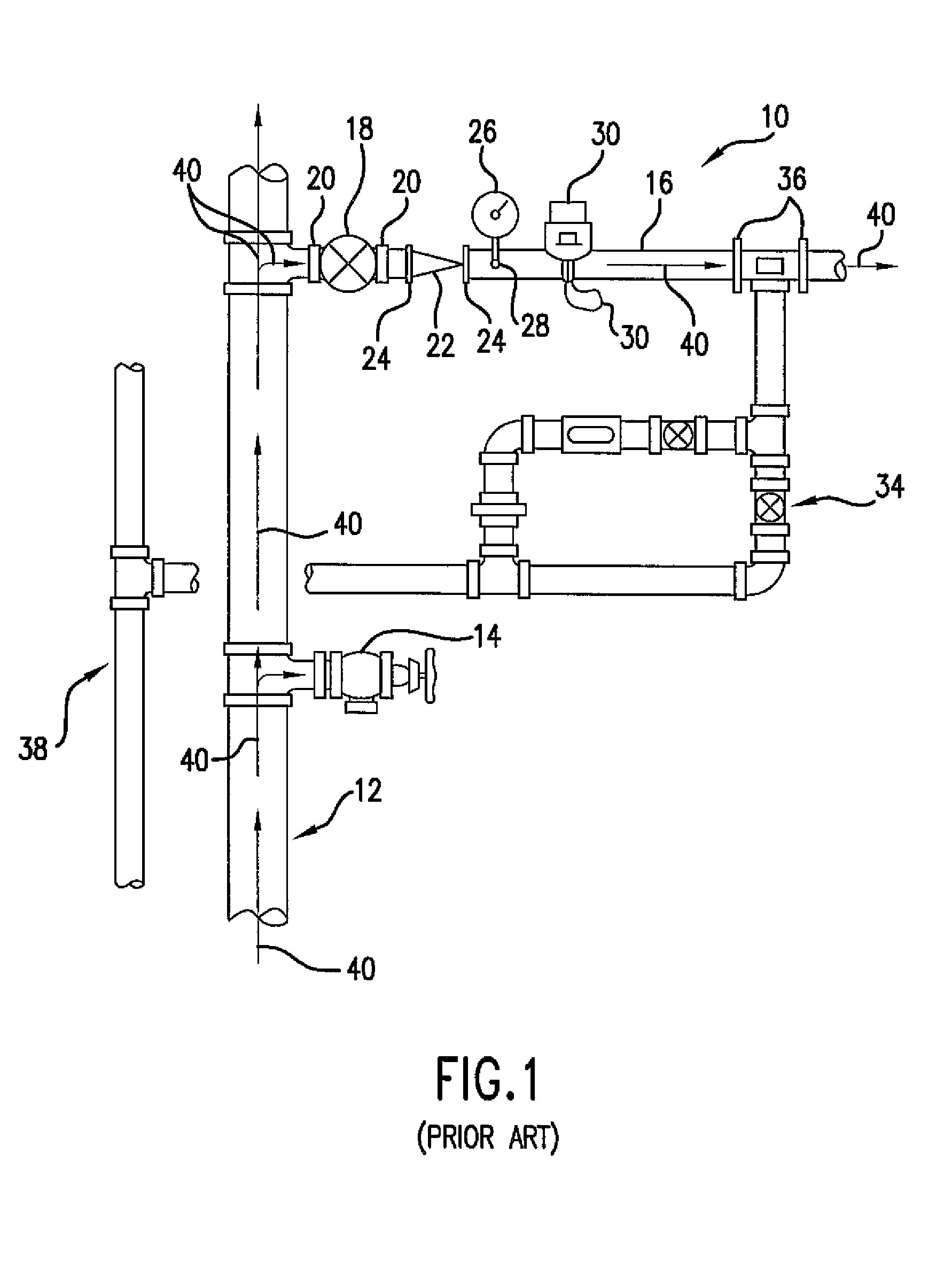
As a result, a large amount of valuable space within the stairwell or other limited mechanical space may be required to accommodate the standpipe riser and the various components.
In addition, each valve and / or component necessitates a break in the main feed line pipes.
As a result, multiple flange-to-flange joints, pipe taps, threaded and / or grooved pipe connections are required, thus providing multiple leak and / or system failure opportunities.

Method used


Image

  • Flow control assembly for a fire sprinkler system
  • Flow control assembly for a fire sprinkler system
  • Flow control assembly for a fire sprinkler system

Examples


Embodiment Construction

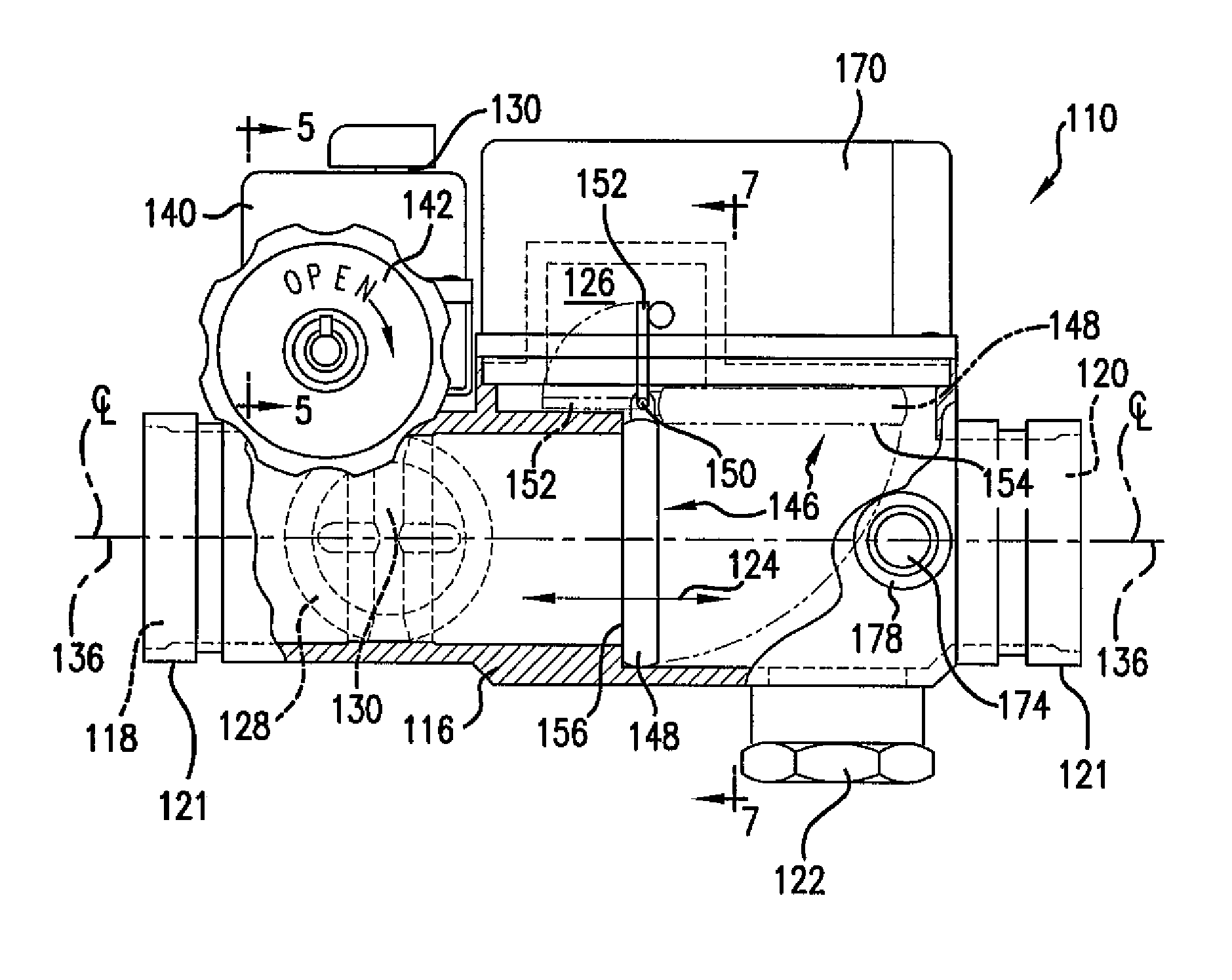
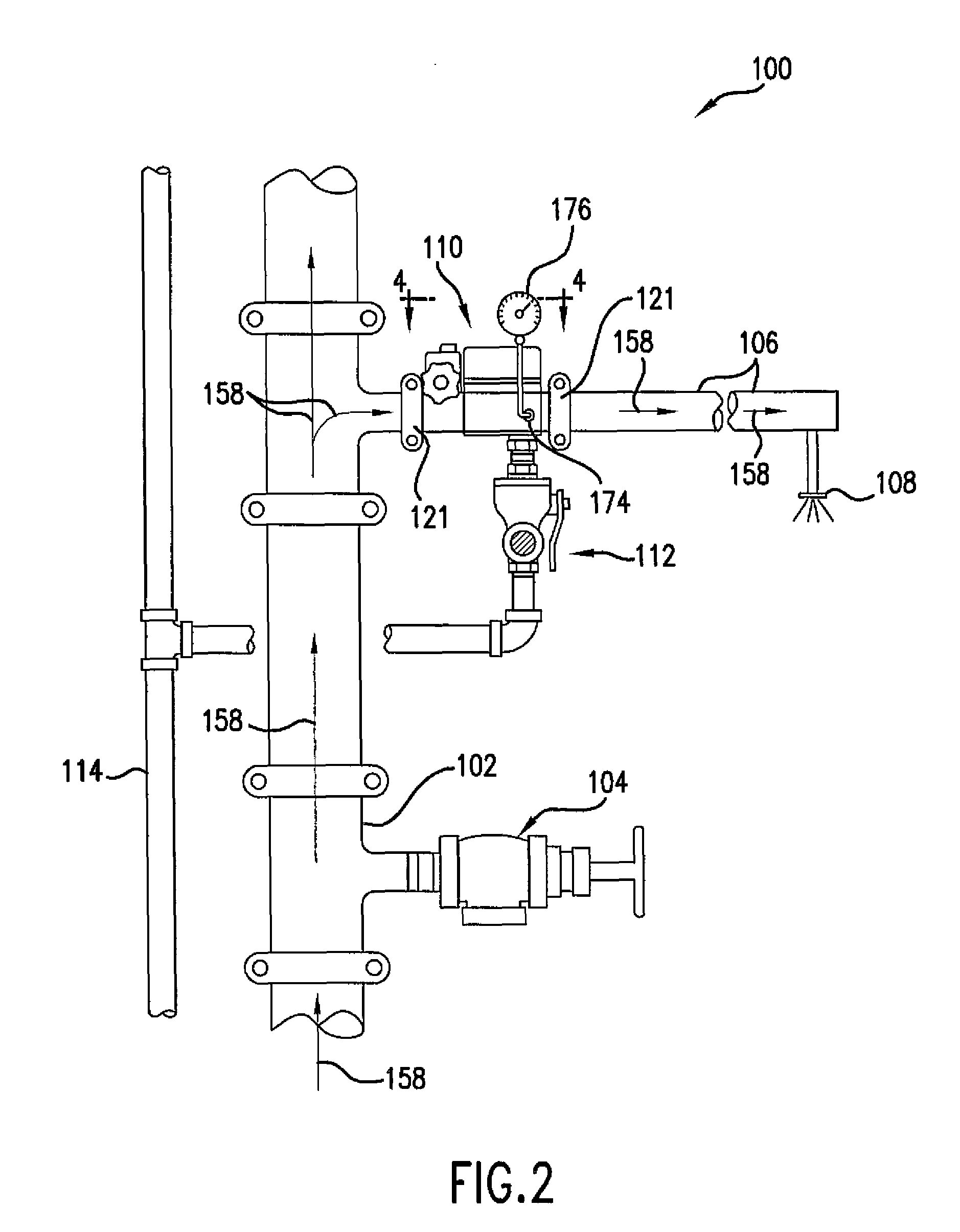
[0018]Reference will now be made in detail to present embodiments of the invention, one or more examples of which are illustrated in the accompanying drawings. The detailed description uses numerical and letter designations to refer to features in the drawings. Like or similar designations in the drawings and description have been used to refer to like or similar parts of the invention. As used herein, the terms “first”, “second”, and “third” may be used interchangeably to distinguish one component from another and are not intended to signify location or importance of the individual components. The terms “upstream” and “downstream” refer to the relative direction with respect to fluid flow in a fluid pathway. For example, “upstream” refers to the direction from which the fluid flows, and “downstream” refers to the direction to which the fluid flows. In addition, the terms “upstream” and “downstream” also implicate the fact that the elements having this relative relationship are conn...


PUM


Abstract

A flow control assembly for a fire sprinkler system includes a valve housing having an inlet opening and an outlet opening. The valve housing defines a fluid flow path that extends between the inlet opening and the outlet opening. A flow control valve is disposed within the fluid flow path. A swing check valve is disposed within the fluid flow path of the valve housing downstream from the flow control valve. The swing check valve includes a clapper that is connected to an actuator arm. An electrical switch is disposed outside of the valve housing. A mechanical linkage includes a first end that extends through the valve housing and engages with the actuator arm. The mechanical linkage also includes a second end that is coupled to the electrical switch. The first end translates with said actuator arm.

Description

FIELD OF THE INVENTION[0001]The present invention generally involves a fire sprinkler system. More specifically, the invention relates to a flow control assembly for controlling a flow of water between a standpipe riser and a sprinkler head of a fire sprinkler system.BACKGROUND OF THE INVENTION[0002]Fire sprinkler systems for multi-story buildings generally include a standpipe riser that is fluidly coupled to one or more sprinkler heads via a main feed line having a plurality of pipes that extend therebetween. Various valves are fluidly connected to the pipes to start, stop or otherwise control the flow of water between the standpipe riser and the sprinkler heads. The fire sprinkler system also may include other separate components such as a flow indicator, a pressure gauge, and alarm system and / or a drainage system.[0003]Typically, the standpipe riser is situated vertically within a stairwell or other limited mechanical space. The valves, the flow indicator and / or the pressure gaug...

Claims


Application Information

Patent Timeline
Patent Type & Authority Patents(United States)
IPC IPC(8): A62C35/68F16K37/00F16K31/54F16K15/18F16K27/02F16K11/20A62C35/60F16K17/28F16K15/03A62C35/58A62C37/50
CPCA62C35/60A62C35/68F16K11/20F16K15/181F16K27/0227F16K31/54F16K37/0008F16K37/0041Y10T137/7069Y10T137/8242Y10T137/8275Y10T137/8326Y10T137/87877Y10T137/88054F16K15/1821
Inventor JOHNSON, AUGUSTUS, W.
Owner JOHNSON CHRISTOPHER W
Learn More