
Member structure for umbrella framework

a member structure and umbrella technology, applied in the direction of walking sticks, etc., can solve the problems of inconvenient, complicated, and inconvenient process of assembling the long bones with the supporting bones, and achieve the effect of improving the member structur

Active Publication Date: 2016-02-23
MA JOEN SHEN
View PDF15 Cites 11 Cited by
  • Summary
  • Abstract
  • Description
  • Claims
  • Application Information

AI Technical Summary

Benefits of technology

The present invention simplifies the structure of the umbrella framework, reduces manufacturing costs, and simplifies assembly. The upper and lower nests, as well as the middle disks, are formed integrally of a same material, eliminating the need for separate parts. Pins on the nests and disks allow for easy connection with the long bones, and the structure of each part requires only a single type of manufacturing material. This simplifies assembly and reduces manufacturing costs. Overall, the present invention improves the efficiency and convenience of the umbrella framework.

Problems solved by technology

Therefore, at least two different materials are required for manufacturing and the process to assemble the long bones with the supporting bones is also complicated and inconvenient.
Similarly, the conventional way to dispose the middle disk in the middle section of each of the long bones is to have the long bone drilled and then pivoted to the supporting bone, or have the metal middle disk fitted over the middle section of the long bone and then have the long bone pivoted to the supporting bone, so this conventional way also has the drawbacks that two different materials are required and the process to assemble the long bones with the supporting bones is complicated.

Method used


Image

  • Member structure for umbrella framework
  • Member structure for umbrella framework
  • Member structure for umbrella framework

Examples


Embodiment Construction

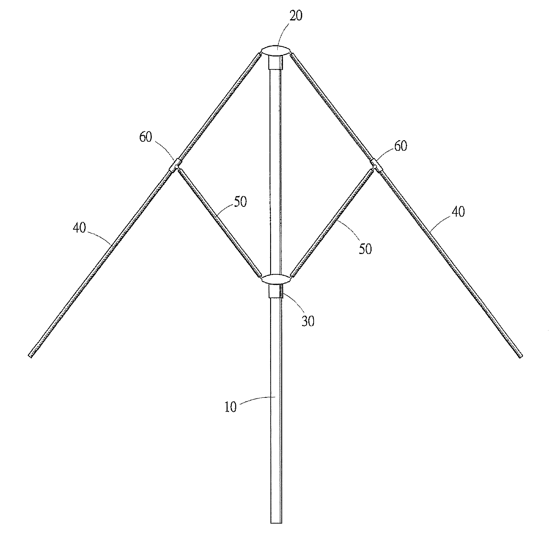
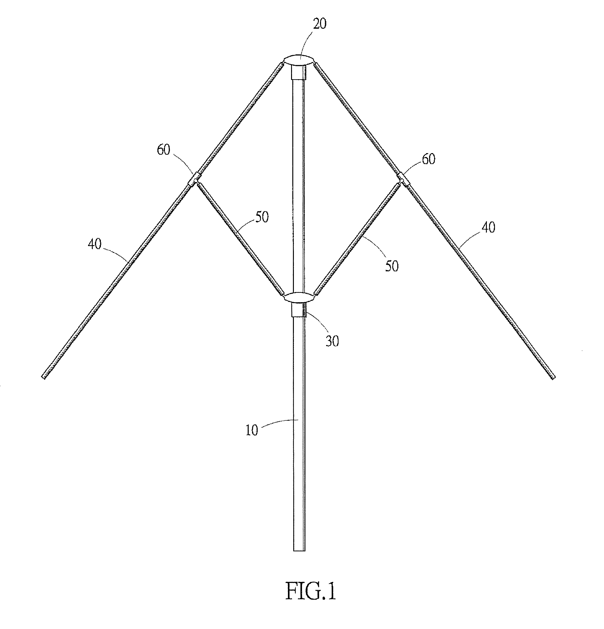
[0027]As shown in FIG. 1, the improved member structure for an umbrella framework of the present invention comprises a middle rod 10, an upper nest 20, a lower nest 30, a plurality of long bones 40, the same number of supporting bones 50, and the same number of middle disks 60.

[0028]As shown in FIG. 1, the upper nest 20 is fixed to a top end of the middle rod 10, and the lower nest 30 is fitted over the middle rod 10 and is capable of sliding up and down.

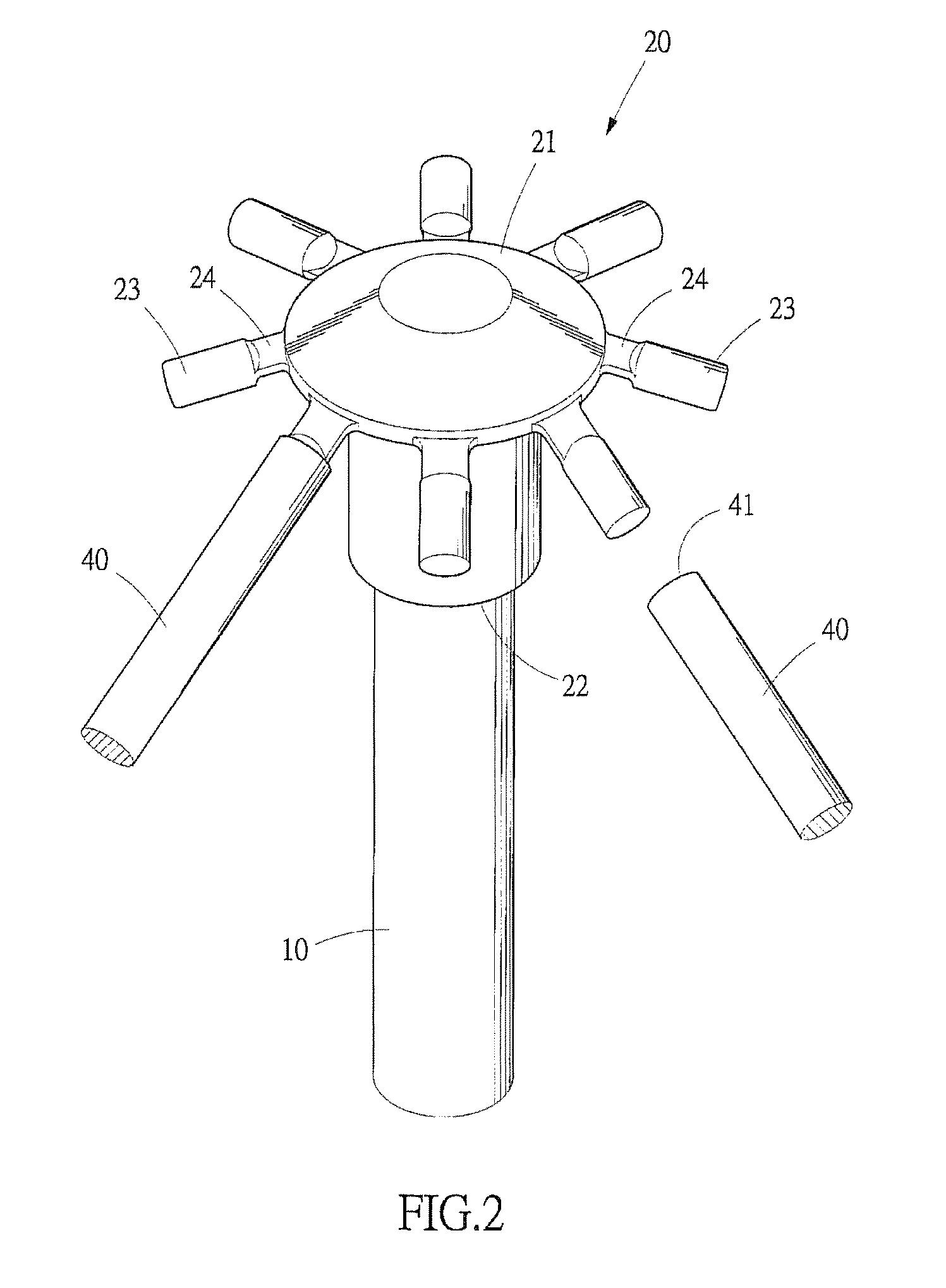
[0029]As shown in FIG. 2 and FIG. 3, the upper nest 20 comprises a nest body 21 and a plurality of pins 23 around a periphery of the nest body 21, an axial hole 22 is disposed at the bottom of the nest body 21 to receive the middle rod 10, each of the pins 23 is integrally connected with the nest body 21 via a connecting section 24, and each of the connecting sections 24 is freely bendable so that each of the pins 23 can swing up and down freely.

[0030]In practical manufacturing, each of the connecting sections 24 is preferably shape...


PUM


Abstract

An upper nest and a lower nest of an umbrella framework each comprise a nest body and a plurality of pins around the nest body. Each pin is integrally connected with the nest body via a connecting section. Each middle disk comprises a pin, which is disposed on an outer wall of a sleeve and integrally connected with the sleeve. Each long bone has an upper end thereof coupled with a pin of the upper nest, and the sleeve of each middle disk is fitted over a middle part of the long bone. Each short bone has an upper end thereof coupled with the pin of the middle disk, and a lower end thereof coupled with a pin of the lower nest. Thereby, an improved member structure for an umbrella framework is formed.

Description

BACKGROUND OF THE INVENTION[0001]1. Technical Field[0002]The present invention relates to an improved member structure for an umbrella framework, and more particularly, to an improved member structure for an umbrella framework of which an upper nest, a lower nest and a middle disk are formed integrally of a same material. As a result, the structure of these three members is simplified, fewer types of manufacturing material are required and the umbrella framework can be assembled more conveniently and rapidly.[0003]2. Description of Related Art[0004]Basic members of conventional umbrella frameworks comprise a middle rod, an upper nest, a lower nest, a plurality of long bones, the same number of supporting bones, and the same number of middle disks. The upper nest is fixed to a top end of the middle rod, and the lower nest is fitted over the middle rod and is capable of sliding up and down. Both the upper nest and the lower nest use metal rings which are disposed thereon or metal wire...

Claims


Application Information

Patent Timeline
Patent Type & Authority Patents(United States)
IPC IPC(8): A45B25/02A45B25/06A45B25/10
CPCA45B25/02A45B25/06A45B25/10
Inventor MA, JOEN-SHEN
Owner MA JOEN SHEN
Learn More