
Debug apparatus and methods for dynamically switching power domains

a dynamic switching and power domain technology, applied in the field of electronic circuits, can solve problems such as inability to cycle hardware through the entire validation space, insufficient time may be available, and problems such as subsequently discovered problems, to achieve the effect of maintaining debugobservability and facilitating debugging operations

Active Publication Date: 2016-02-16
ADVANCED MICRO DEVICES INC
View PDF13 Cites 1 Cited by
  • Summary
  • Abstract
  • Description
  • Claims
  • Application Information

AI Technical Summary

Benefits of technology

This patent describes methods and apparatus for debugging complex integrated circuits that have different power domains. The invention involves a bug data register that can capture and store data provided to the debugging circuit of a controlled sector when the sector is powered off. This data is then used to restore the debugging circuit to the state it was in when the sector was previously powered on. This invention enables improved debugging of integrated circuits, even during power events.

Problems solved by technology

One challenge is to do a thorough job so that ICs are not deployed in the field, and then significant problems are subsequently discovered (e.g., by an original equipment manufacturer (OEM)).
However, this is not always possible.
One reason is that insufficient time may be available for cycling the hardware through the entire validation space.
Another reason is that certain aspects of the hardware and state machine functionality are opaque (i.e., not easily observable).
Such circuits present additional issues in the testing of ICs.

Method used


Image

  • Debug apparatus and methods for dynamically switching power domains
  • Debug apparatus and methods for dynamically switching power domains
  • Debug apparatus and methods for dynamically switching power domains

Examples


Embodiment Construction

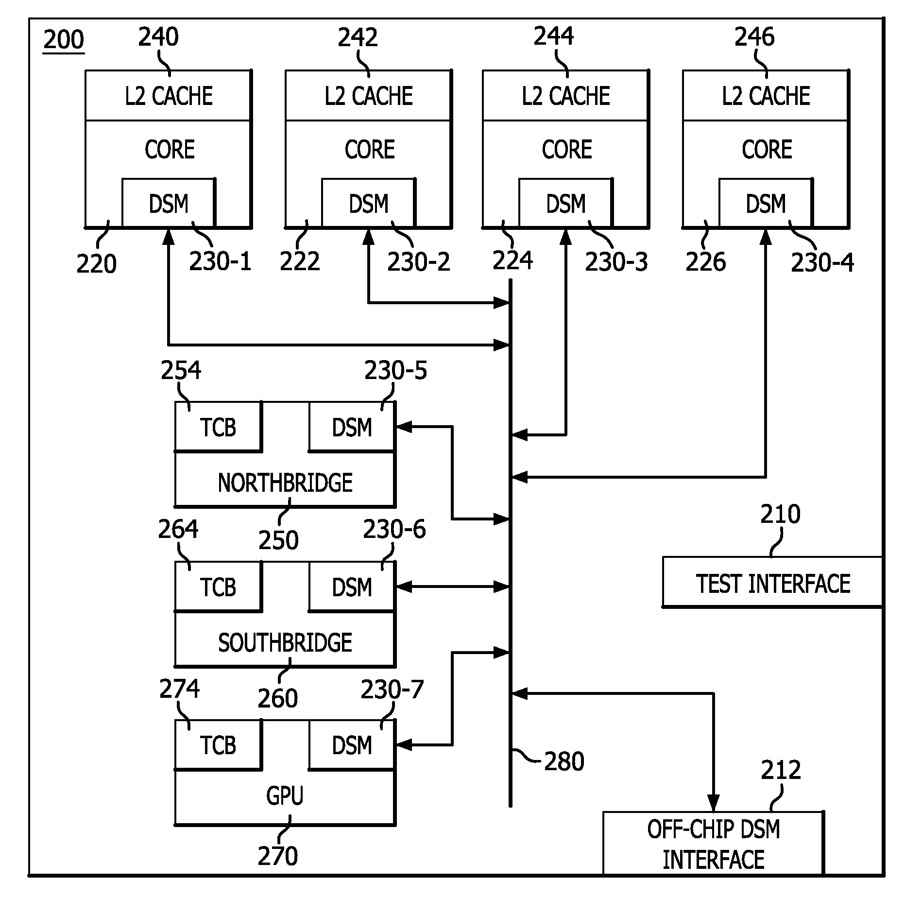
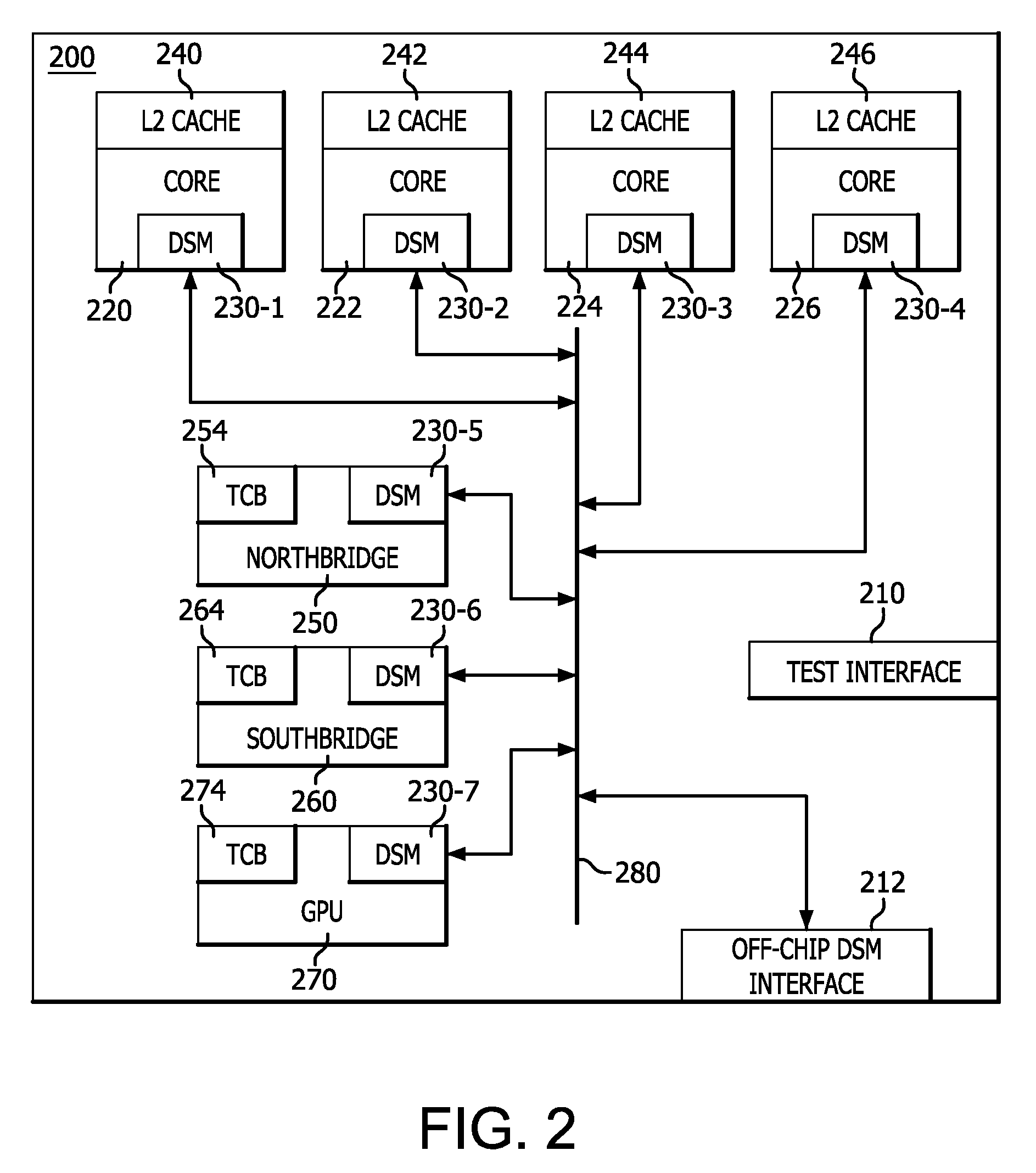
[0005]Methods and apparatus are provided that facilitate debugging operations for components that may include different power domains. In an embodiment, an integrated circuit (IC) includes a plurality of hardware sectors, each hardware sector associated with a debug observability circuit that is served by a debug data bus of a debug circuit. The plurality of hardware sectors includes a controlled sector residing in a dynamically-controlled power domain that may be turned off while the power domain of another sector remains on. However, the need is to be able to maintain debug observability all the way through these power events. To address that a debug data register is configured to provide data, such as configuration and / or programming data, to the debug observability circuit of the controlled sector via the debug data bus. A shadow register is configured to receive and store the data provided to the debug observability circuit of the controlled sector. Control circuitry is configu...


PUM


Abstract

Methods and apparatus are provided that facilitate debugging operations for components in dynamic power domains. In an embodiment, an integrated circuit includes hardware sectors associated with observability circuits served by a debug data bus of a debug circuit. A controlled sector residing in a dynamically-controlled power domain may be turned off while the power domain of another sector remains on. To continue to have debug observability all the way through and after these power events, a debug data register is configured to provide data, such as configuration and / or programming data, to the observability circuit of the controlled sector via the debug data bus. A shadow register is configured to capture the data provided to the controlled sector's observability circuit. The shadow register data is used upon restoring power to the controlled sector to restore the controlled sector's observability circuit to a state when the controlled sector was previously powered on.

Description

FIELD OF INVENTION[0001]Embodiments of the subject matter described herein relate generally to electronic circuits, and more particularly, relate to electronic circuits and debug operations performed thereon.BACKGROUND[0002]In development process of an integrated circuit (IC), it is desirable to ensure that the hardware works correctly in the expected operating space before the IC is shipped in volume. Generally, the use of debug circuits and processes are well known in art to assist in the testing of ICs. U.S. Patent Publication No. 2012 / 0151263 A1 describes various embodiments of debug circuits and processes.[0003]One challenge is to do a thorough job so that ICs are not deployed in the field, and then significant problems are subsequently discovered (e.g., by an original equipment manufacturer (OEM)). However, this is not always possible. One reason is that insufficient time may be available for cycling the hardware through the entire validation space. Another reason is that cert...

Claims


Application Information

Patent Timeline
Patent Type & Authority Patents(United States)
IPC IPC(8): G06F11/00G06F11/27G01R31/317
CPCG06F11/27G01R31/31705G01R31/31721
Inventor SARANGI, SHANTANU K.RENTSCHLER, ERICDEV, RAHULCHOPRA, VIKRAMDOCTOR, MIHIR
Owner ADVANCED MICRO DEVICES INC
Learn More