
Tufting machine drive system

a technology of drive system and tufting machine, which is applied in the direction of tufting apparatus, etc., can solve the problems of limited load support capacity increased or more rapid wear, and limited use of such ball bearings or bushings, so as to facilitate the adjustment of length and promote greater dimensional stability of tufting fabrics

Inactive Publication Date: 2016-02-16
CARD MONROE
View PDF68 Cites 17 Cited by
  • Summary
  • Abstract
  • Description
  • Claims
  • Application Information

AI Technical Summary

Benefits of technology

The present invention is a drive system for controlling and facilitating the multi-directional movement of various driven operative elements of a tufting machine. The system can provide enhanced rigidity and dimensional stability to the needle bar(s) during reciprocating and shifting movements, which can enable tighter control and improved precision of multi-directional movements of the needle bar. This results in increased operational speeds and reduced wear of the drive system components at increased operating speeds. The system can also be used for driving other operative elements of the tufting machine, such as the shifting mechanism for controlling the lateral shifting or stepping of the needle bars. The system includes a second directional drive component that links the needle bar to a shifting mechanism for forming desired tufting patterns. The system also includes a support bracket that can be adjusted to different needs without replacing the entire push rod. The system can provide greater dimensional stability to the tufted fabrics being formed and reduce excessive wear of the drive system components at increased operating speeds.

Problems solved by technology

The use of such ball bearings or bushings, however, often is limited in terms of the loads they can support, especially at higher machine operating speeds, and further can be subject to increased or more rapid wearing at such increased operating speeds.
However, at such higher reciprocation / operational speeds, it becomes difficult to accurately control shifting of the needle bars, and the drive systems further can be subjected to increased vibrational forces as well as increased heat and wear due to the effects of the friction between the hardened shafts and ball bearings / bushings traditionally used for guiding the shift rods and push rods of such needle bar drive systems.

Method used


Image

  • Tufting machine drive system
  • Tufting machine drive system
  • Tufting machine drive system

Examples


Embodiment Construction

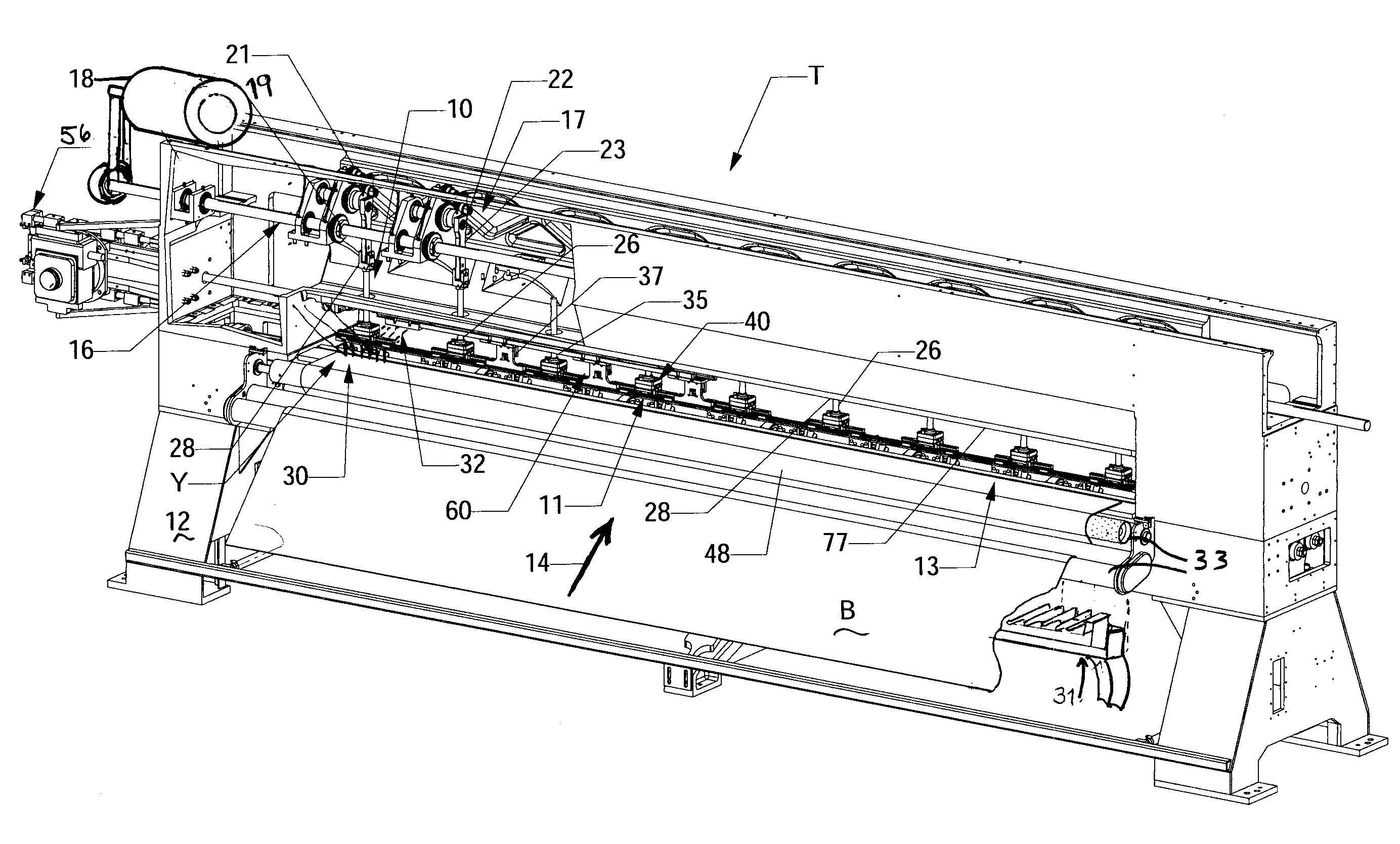
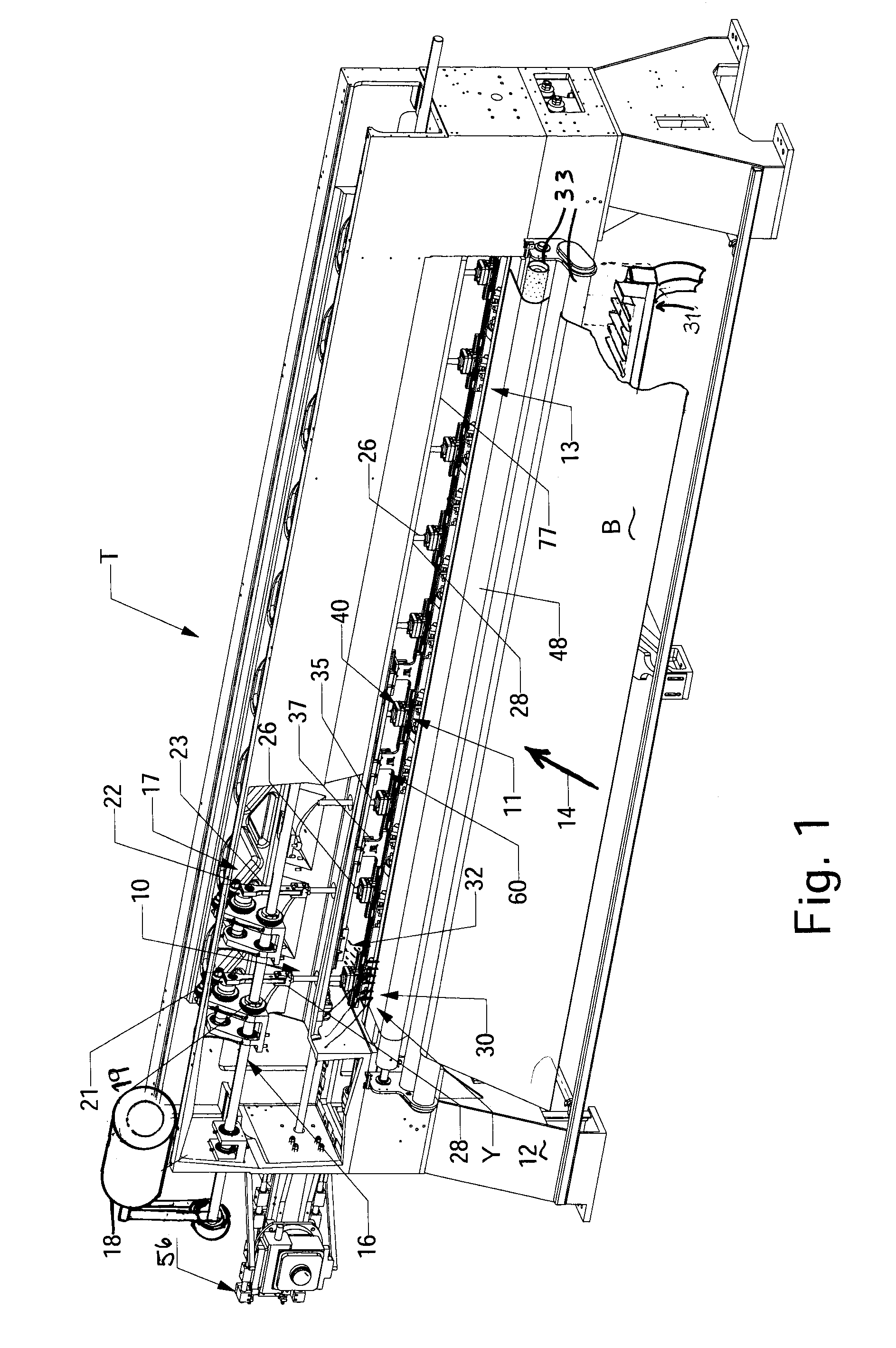
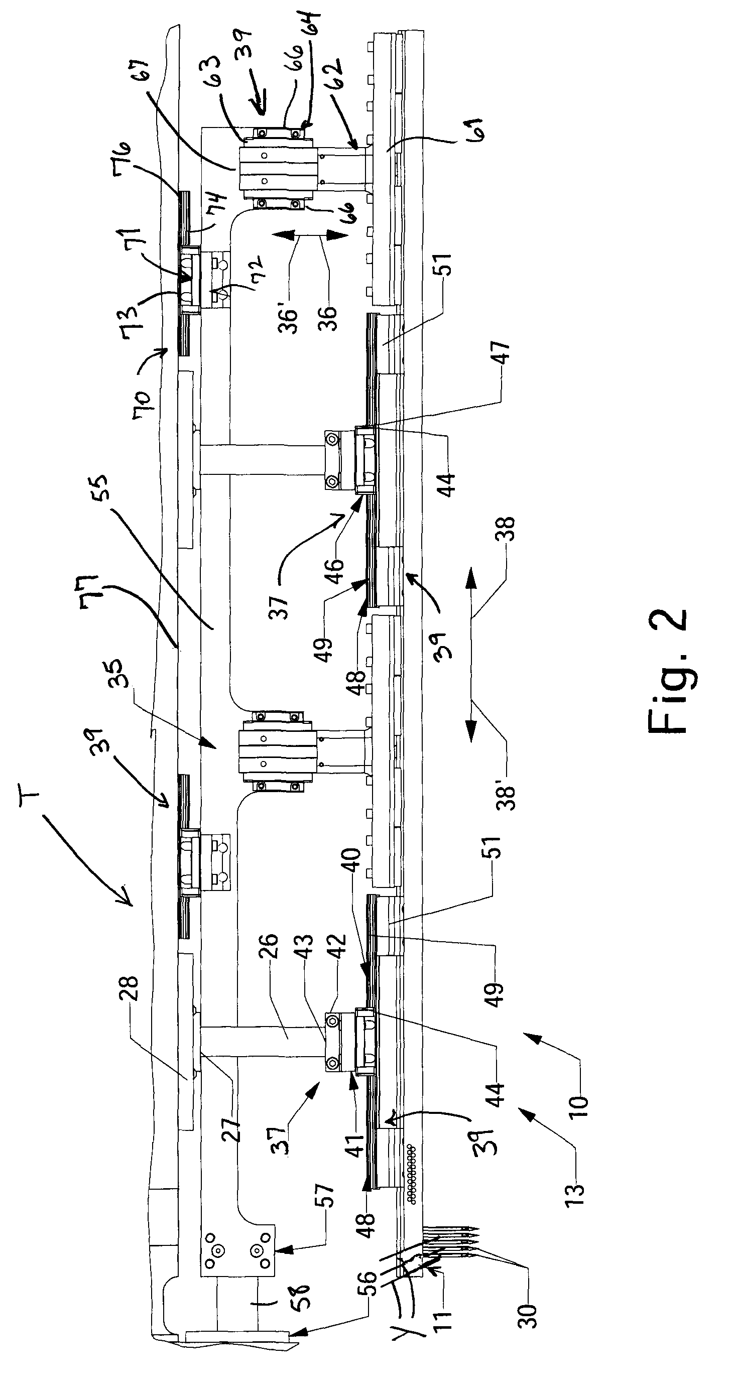
[0025]Referring now to the drawings in which like numerals indicate like parts throughout the several views, the present invention is directed to a drive system for the control of driven operative elements of various types of machines, and in particular the driving of operative elements or components of a tufting machine. In one example embodiment, as shown in FIGS. 1-7, the drive system 10 of the present invention will be directed to a system for controlling the motion of a needle bar 11, or pair of needle bars, of a tufting machine T (FIG. 1), as the needle bar is reciprocated in a first direction, i.e., a vertical direction, and further is moved in at least one additional or secondary direction (i.e., a lateral or shifting direction) that is different from the first direction of movement of the needle bar. The drive system 10 is designed to provide enhanced rigidity and stability to the needle bar as the needle bar is reciprocated / moved in multiple, different directions for formi...


PUM


Abstract

A tufting machine has a needle bar for carrying a plurality of needles for reciprocating into and out of a base material. A sliding needle bar shift mechanism may shift the needle bar laterally according to a pattern. The needle bar is mounted for reciprocation and for lateral movement relative to the direction of reciprocation by a drive system including a first directional drive component having a foot secured to a respective push rod of the tufting machine and a second directional drive component connected to the shift mechanism. The first and second drive components will connect to the needle bar through linear bearings or bushings so that the motion of the needle bar in multiple different directions is controlled while permitting greater machine operating and needle bar shifting speeds.

Description

CROSS REFERENCE TO RELATED APPLICATIONS[0001]The present patent application is a formalization of previously filed, U.S. Provisional Patent Application Ser. No. 61 / 828,412, filed May 29, 2013 by the inventors named in the present application. This patent application claims the benefit of the filing date of this cited Provisional Patent Application according to the statutes and rules governing provisional patent applications, particularly 35 U.S.C. §119(a)(i) and 37 C.F.R. §1.78(a)(4) and (a)(5). The specification and drawings of the Provisional Patent Application referenced above are specifically incorporated herein by reference as if set forth in their entireties.FIELD OF THE INVENTION[0002]The present invention generally relates to machine drive systems in which operative elements are designed to be driven or reciprocated in multiple, different directions. In particular, the present invention is directed to a drive system for tufting machines for use in guiding and controlling mov...

Claims


Application Information

Patent Timeline
Patent Type & Authority Patents(United States)
IPC IPC(8): D05C15/20D05C15/30D05C15/10
CPCD05C15/30D05C15/20D05C15/10D05C15/12
Inventor NEELY, MARSHALL ALLENMATHEWS, RICKY E.GIBSON, DARYL L.
Owner CARD MONROE
Learn More