Electromechanical removable grip mechanism

a technology of electronic mechanical and removable grip, which is applied in the field of removable grip mechanism, can solve the problems of reducing the storage space required for utensils and being inability to use, and achieve the effect of convenient us

Active Publication Date: 2016-02-16
SEB SA
View PDF9 Cites 0 Cited by
  • Summary
  • Abstract
  • Description
  • Claims
  • Application Information

AI Technical Summary

Benefits of technology

[0006]Accordingly, the invention is designed to resolve these inconveniences and provide a remov...

Problems solved by technology

The removable grip mechanism may also include additional functions, which are not possible with handles of the prior art, which assist in cooking.
The multi-function...

Method used


Image

  • Electromechanical removable grip mechanism
  • Electromechanical removable grip mechanism
  • Electromechanical removable grip mechanism

Examples


Embodiment Construction

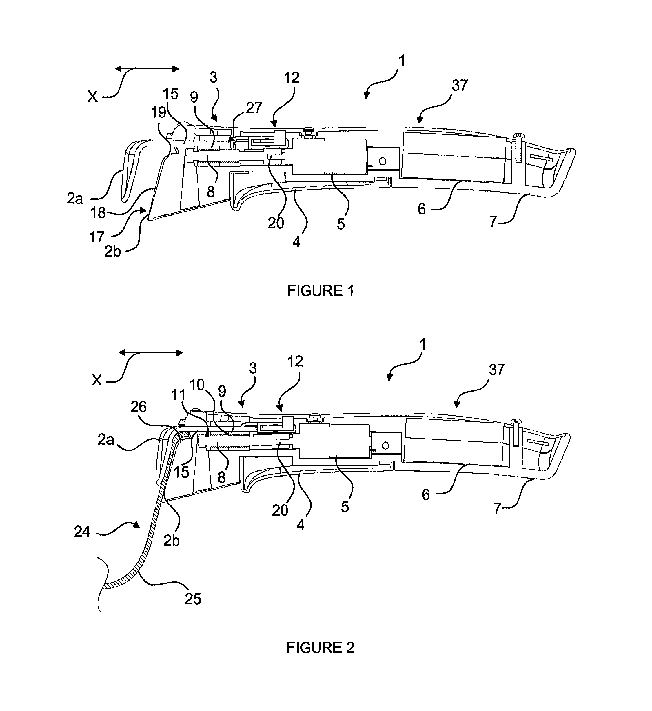
[0037]Removable grip mechanism 1 includes grip body 7, the mechanism to attach it to and disconnect it from cooking pot 24, and electrical energy source 6. Removable grip mechanism 1 includes electromechanical mechanism 5, 5a, 5b and 5c powered by energy source 6 to trigger a mechanical mechanism and command mechanism 4, 12, 22 and 56 to control the operation of and stop electromechanical mechanism 5, 5a, 5b and 5c.

[0038]The attachment mechanism may include pincer-type mobile bits which are activated manually or motorized as described below, for example. In one variation, the attachment mechanism may include hooks which are part of removable grip mechanism 1 which are designed to be inserted into one of the openings on side wall 25 of cooking pot 24. Other attachment mechanisms are also possible such as, for example, a nut-bolt system.

[0039]Preferably, the mechanical mechanism includes the attachment mechanism. Removable grip mechanism 1 includes trigger mechanism 3 driven by elect...


PUM


Abstract

Provided is a removable grip device (1) for a pot for cooking food, said removable grip device (1) comprising a grip body (7), attachment means that can be connected to the cooking pot and disconnected therefrom, and an electrical energy source (6). The removable grip device (1) comprises an electromechanical device fed by the energy source (6) and suitable for actuating a mechanical device, and control means for controlling the operation and the shut-off of the electromechanical device.

Description

CROSS-REFERENCE TO RELATED APPLICATIONS[0001]This application is the United States national phase of International Application No. PCT / FR2012 / 051575 filed Jul. 5, 2012, and claims priority to French Patent Application No. 1156378 filed Jul. 13, 2011, the disclosures of which are hereby incorporated in their entirety by reference.FIELD OF THE INVENTION[0002]This invention concerns a removable grip mechanism for a cooking pot.[0003]Removable grip mechanisms or removable handles are used to grip cooking pots such as casseroles or frying pans. Removable grip mechanisms may be fixed temporarily to a cooking pot when in use and be removed from the cooking pot to make it easier to store.DESCRIPTION OF THE RELATED ART[0004]Document EP 0 769 263 which discloses a removable grip mechanism for a cooking pot which includes a side wall. The grip mechanism includes two bits which form a pincer which moves between an open and closed position in which the two bits which form a pincer grip the side ...

Claims


Application Information

Patent Timeline
IPC IPC(8): B65D25/28A47J45/10A47J45/07
CPCA47J45/071A47J45/10B65D25/282
Inventor BONNEL, JOCELYNMONTGELARD, MICHELHERRADA, JOSE LUIS
Owner SEB SA
Why Eureka
Try Eureka