
Method and apparatus for controlling the flow of packets in a data network

a data network and packet control technology, applied in electrical devices, data switching networks, digital transmission, etc., can solve the problems of overflow of incoming frames to a device, complex task of managing the flow of frames between devices on a data network, and device overload,

Active Publication Date: 2016-01-26
MARVELL ASIA PTE LTD
View PDF14 Cites 2 Cited by
  • Summary
  • Abstract
  • Description
  • Claims
  • Application Information

AI Technical Summary

Benefits of technology

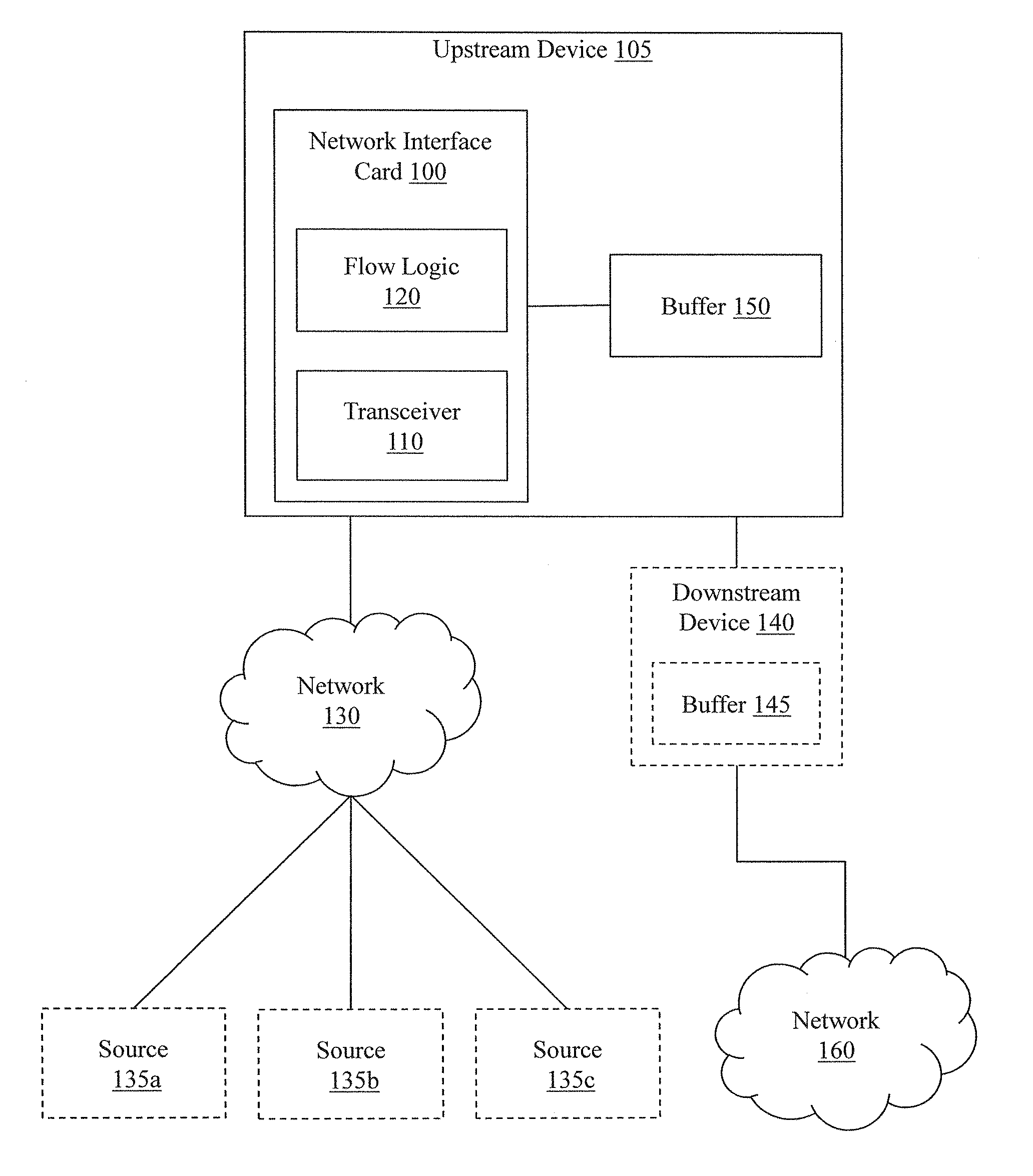
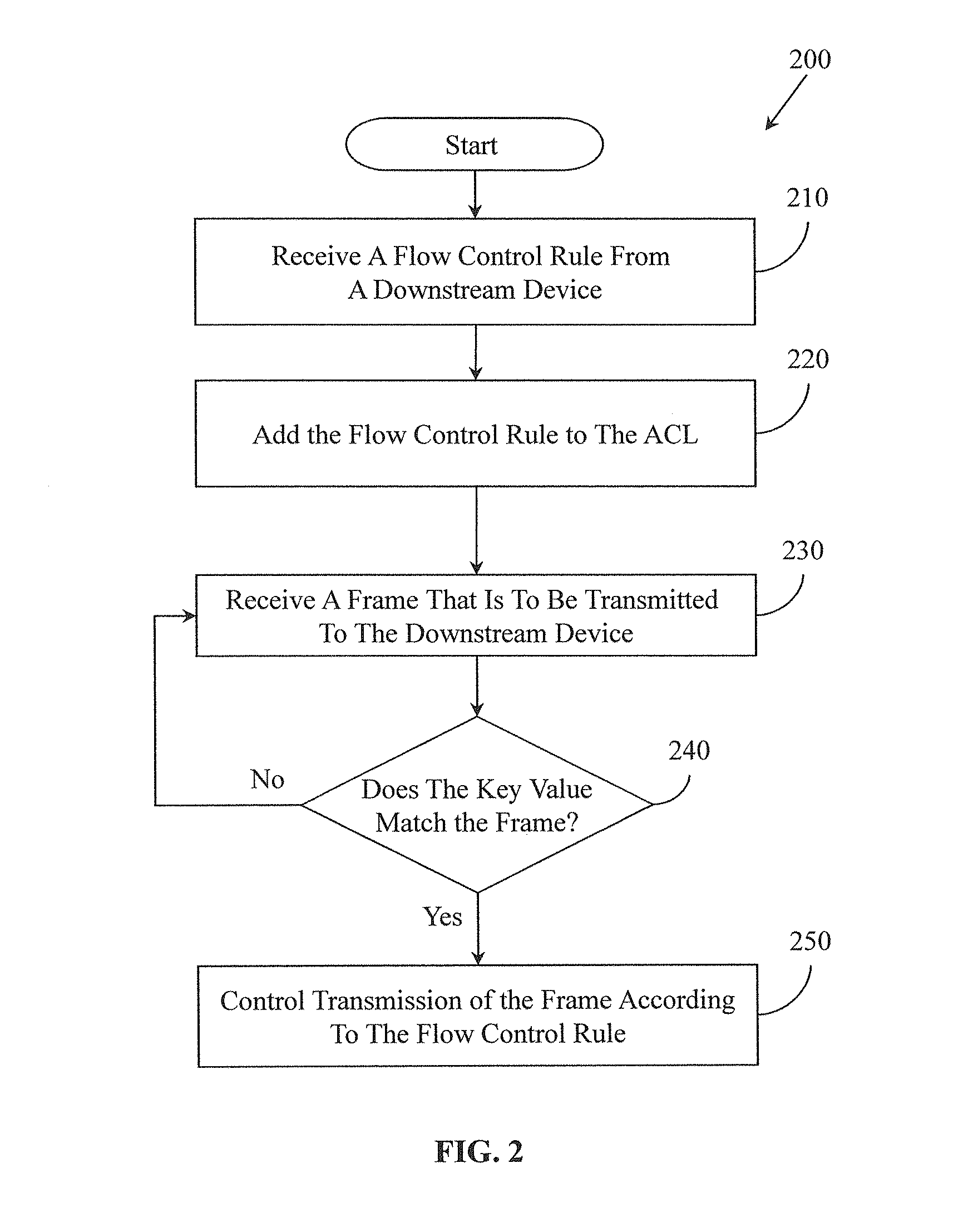
The patent relates to a system that includes a transceiver and flow logic. The flow logic is responsible for controlling the transceiver to transmit a frame to a downstream device based on a predetermined pattern that identifies the source of the frame. The predetermined pattern contains information about the type of action that needs to be performed on the frames that are received from the source and are to be transmitted to the downstream device. The system uses this information to automatically control the transmission of the frame to the downstream device. This makes the process of transmitting frames much faster and more efficient, reducing the time and effort required by network administrators.

Problems solved by technology

Inevitably, some of the devices may become busy due to the devices being located centrally within a data network (e.g., centralized hop points), while other devices, e.g., on peripheral arteries, may experience less traffic within a data network.
Accordingly, managing the flow of frames between devices on a data network can be a complex task.
For example, the flow of incoming frames to a device (e.g., centralized device) can exceed the device's ability to provide the frames downstream.
However, if this condition persists for an extended period of time, the internal memory of the device can become full, thus causing frames to be dropped.
While this approach provides a basic solution to minimize the dropping of frames during times of peak traffic, difficulties with, for example, frames that are time sensitive can arise due to increased wait times while the frames are buffered.

Method used


Image

  • Method and apparatus for controlling the flow of packets in a data network
  • Method and apparatus for controlling the flow of packets in a data network
  • Method and apparatus for controlling the flow of packets in a data network

Examples


examples

[0045]1) Permit frames from source A for X seconds. This flow control rule explicitly allows frames from source A to be transmitted for the specified time frame regardless of any other flow control rule that may pause or drop the frames from source A.

[0046]2) Pause frames with a CoS< five while Permitting frames from Source A. This flow control rule pauses a frame if the CoS level is less than five, but allows frames from source A regardless of a CoS level.

[0047]3) Redirect frames from source A to destination Y for the next X seconds. This flow control rule redirects frames from source A to a destination Y for a time period defined by X. This example illustrates how the flow control rule can redirect packets around the downstream device while, for example, the downstream device is busy. While the new destination Y may not be a shortest route to a final destination, it still permits the frame to be communicated instead of being paused at the upstream device.

[0048]4) Pause frames from...


PUM


Abstract

Systems, methods, and other embodiments associated with controlling the flow of packets in a network are described. According to one embodiment, an apparatus includes a transceiver and a flow logic. The flow logic is configured to control the transceiver to transmit a frame to a downstream device by determining whether the frame matches a predetermined pattern. The predetermined pattern identifies a source of frames. The predetermined pattern specifies an action to perform for frames received from the source that are to be transmitted to the downstream device. The flow logic is also configured to control the transceiver to transmit a frame to a downstream device by, in response to determining that the frame matches the predetermined pattern, controlling transmission of the frame to the downstream device according to the action specified by the predetermined pattern.

Description

CROSS REFERENCE TO RELATED APPLICATIONS[0001]This patent disclosure is a continuation of U.S. patent application Ser. No. 13 / 488,537 filed on Jun. 5, 2012, now U.S. Pat. No. 8,873,392; which claims the benefit of U.S. Provisional Application No. 61 / 494,972 filed on Jun. 9, 2011.BACKGROUND[0002]The background description provided herein is for the purpose of generally presenting the context of the disclosure. Work of the presently named inventor(s), to the extent the work is described in this background section, as well as aspects of the description that may not otherwise qualify as prior art at the time of filing, are neither expressly nor impliedly admitted as prior art against the present disclosure.[0003]In data networks, a frame of data (referred to herein generally as a “frame” or a “packet”) is often communicated between a sequence of devices (e.g., switches and routers) in order to reach a destination. Such a sequence of devices is commonly referred to as hops in a network pa...

Claims


Application Information

Patent Timeline
IPC IPC(8): G01R31/08H04L12/851
CPCH04L47/2483H04L47/2458H04L47/2475H04L47/263H04L47/323H04L47/2441
Inventor ORR, MICHAEL
Owner MARVELL ASIA PTE LTD
Learn More