Light guide plate and area light source device
a technology of light guide plate and light source device, which is applied in the direction of optical waveguide light guide, optical light guide, instrument, etc., can solve the problems of reducing the height of a light source including an led, reducing the effective lighting area, and reducing the light quantity, so as to achieve the effect of preventing the narrowing of the effective lighting area and widened the effective lighting area
- Summary
- Abstract
- Description
- Claims
- Application Information
AI Technical Summary
Benefits of technology
Problems solved by technology
Method used
Image
Examples
first embodiment
Configuration of First Embodiment
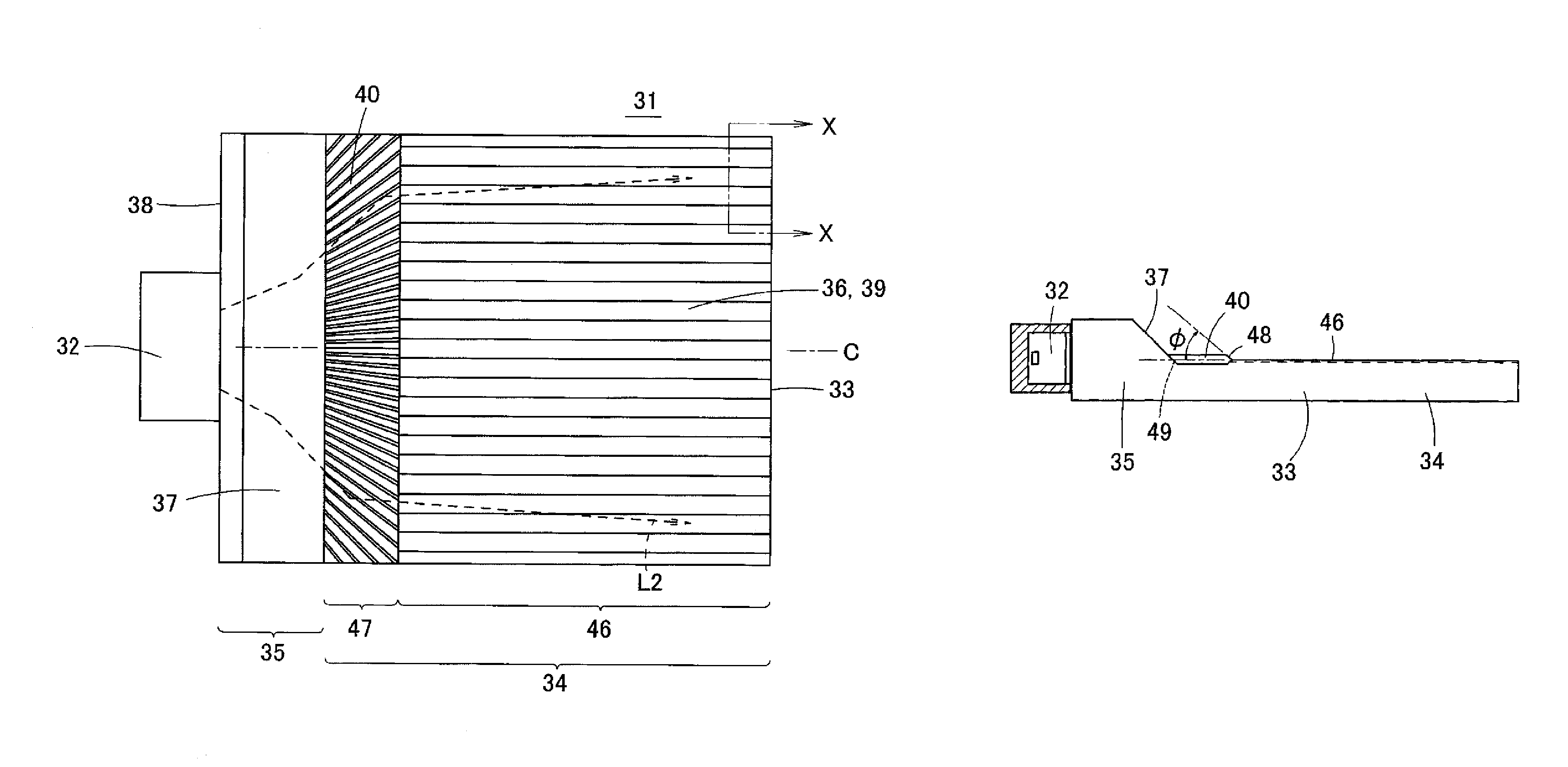
[0056]A configuration of a first embodiment of the present invention will be described below with reference to FIGS. 6A, 6B, 7, and 8. FIG. 6A is a plan view illustrating an area light source device 31 of the first embodiment. FIG. 6B is an enlarged sectional view taken on a line X-X in FIG. 6A, and illustrates a lenticular lens 36 provided on a surface of a light guide plate 33. FIG. 7 is a schematic sectional view along a vertical direction (a direction perpendicular to a light incident surface 38) of the area light source device 31, and illustrates a behavior of light beam in the light guide plate 33. FIG. 8 is a sectional view illustrating a shape of a directivity change pattern in a section parallel to a light incident surface and a partially enlarged section of the directivity change pattern. Because the area light source device 31 of the first embodiment is also illustrated by the perspective view in FIG. 3, the area light source device 31 of ...
second embodiment
[0098]FIG. 17 is a perspective view illustrating an area light source device 71 according to a second embodiment of the present invention. FIG. 18A is a plan view of the area light source device 71. FIG. 18B is a sectional view taken on a line Y-Y in FIG. 18A.
[0099]In the area light source device 71 of the second embodiment, a light diffusion pattern 72 is formed on the upper surface and / or lower surface of the light introduction part 35 in order to horizontally spread the directivity of the reflected light. As illustrated in FIG. 18B, the light diffusion pattern 72 may be formed by arraying vertically-extending V-grooves 72a in parallel with one another, or the light diffusion pattern 72 may be a pattern having a lenticular-lens shape or a random shape. In the structure of the second embodiment, the light is sent to the side surface direction of the light guide plate 33 while horizontally spread by the light diffusion pattern 72, thereby preventing darkening of a side edge portion ...
third embodiment
[0102]FIG. 20 is a plan view illustrating an area light source device 81 according to a third embodiment of the present invention. FIG. 21 is a partially enlarged perspective view illustrating the light introduction part 35 of the area light source device 81.
[0103]In the area light source device 81 of the third embodiment, a light diffusion pattern 82 that horizontally spreads the light is provided in a region facing at least the light source 32 in the light incident surface 38 of the light introduction part 35. As illustrated in FIG. 21, the light diffusion pattern 82 may be formed into a cylindrical lens shape in which the convex lenses extending in the height direction are horizontally arrayed. Alternatively, the light diffusion pattern 82 may be constructed by arraying the V-grooves extending in the height direction in parallel with one another, or the light diffusion pattern 82 may be a pattern having a random shape.
[0104]In the area light source device 81 having the above stru...
PUM
 Abstract
Description
Claims
Application Information
 - R&D
- Intellectual Property
- Life Sciences
- Materials
- Tech Scout
- Unparalleled Data Quality
- Higher Quality Content
- 60% Fewer Hallucinations
Browse by: Latest US Patents, China's latest patents, Technical Efficacy Thesaurus, Application Domain, Technology Topic, Popular Technical Reports.
© 2025 PatSnap. All rights reserved.Legal|Privacy policy|Modern Slavery Act Transparency Statement|Sitemap|About US| Contact US: help@patsnap.com


